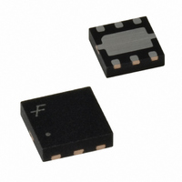
FAN2558MP15X Fairchild Semiconductor, FAN2558MP15X Datasheet - Page 6

FAN2558MP15X
Manufacturer Part Number
FAN2558MP15X
Description
IC REG LDO 180MA 1.5V 2X2 6MLP
Manufacturer
Fairchild Semiconductor
Datasheet
1.FAN2558S33X.pdf
(15 pages)
Specifications of FAN2558MP15X
Regulator Topology
Positive Fixed
Voltage - Output
1.5V
Voltage - Input
2.7 ~ 5.5 V
Number Of Regulators
1
Current - Output
180mA (Max)
Current - Limit (min)
260mA
Operating Temperature
-40°C ~ 85°C
Mounting Type
Surface Mount
Package / Case
6-MLP
Number Of Outputs
1
Polarity
Positive
Input Voltage Max
5.5 V
Output Voltage
1.5 V
Output Type
Fixed
Dropout Voltage (max)
400 mV
Output Current
180 mA
Line Regulation
0.3 % / V
Load Regulation
2.5 %
Voltage Regulation Accuracy
1 %
Maximum Operating Temperature
+ 125 C
Mounting Style
SMD/SMT
Minimum Operating Temperature
- 40 C
Lead Free Status / RoHS Status
Lead free / RoHS Compliant
Voltage - Dropout (typical)
-
Lead Free Status / Rohs Status
Lead free / RoHS Compliant
Functional Description
Utilizing BiCMOS technology, the FAN2525/FAN2559
product family is optimized for use in compact battery pow-
ered systems. These LDOs offer a unique combination of
high ripple rejection, low noise, low power consumption,
high tolerance for a variety of output capacitors, and less
than 1µA “OFF” current. In the circuit, a differential current
sense amplifier controls a series-pass P-Channel MOSFET to
achieve high ripple rejection. A separate error amplifier com-
pares the load voltage at the output with an onboard trimmed
low voltage bandgap reference for output regulation.
Thermal shutdown and current limit circuits protect the
device under extreme conditions. When the device tempera-
ture reaches 150°C, the output is disabled. When the device
cools down by 10°C, it is re-enabled. The user can shut down
the device using the Enable control pin at any time. The cur-
rent limit circuit is trimmed, which leads to consistent power
on /enable delays, and provides safe short circuit current
densities even in narrow traces of the PCB.
A carefully optimized control loop accommodates a wide
range of ESR values in the output bypass capacitor, allowing
the user to optimize space, cost, and performance require-
ments.
An Enable pin shuts down the regulator output to conserve
power, reducing supply current to less than 1µA.
The fixed-voltage FAN2559 has a noise bypass pin. Power
Good is available as a diagnostic function to indicate that the
output voltage has reduced within 5% of the nominal value.
The six pin adjustable-voltage version utilizes pin 5 to con-
nect to an external voltage divider which feeds back to the
regulator error amplifier, thus setting the output voltage to
the desired value.
Applications Information
External Capacitors – Selection
The FAN2558/FAN2559 gives the user the flexibility to uti-
lize a wide variety of capacitors compared to other LDOs.
An innovative design approach offers significantly reduced
sensitivity to ESR, which degrades regulator loop stability in
older designs. While the improvements featured in the
FAN2558/FAN2559 family greatly simplify the design task,
6
FAN2558/FAN2559
capacitor quality still must be considered if the designer is to
achieve optimal circuit performance. In general, ceramic
capacitors offer superior ESR performance, and a smaller
case size than tantalum capacitors.
Input Capacitor
An input capacitor of 2.2µF (nominal value) or greater,
connected between the Input pin and Ground, placed in close
proximity to the device, will improve transient response and
ripple rejection. Higher values will further improve ripple
rejection and transient response. An input capacitor is rec-
ommended when the input source, either a battery or a regu-
lated AC voltage, is located far from the device. Any good
quality ceramic, tantalum, or metal film capacitor will give
acceptable performance; however, in extreme cases capacitor
surge current ratings may have to be considered.
Output Capacitor
An output capacitor is required to maintain regulator loop
stability. Stable operation will be achieved with a wide vari-
ety of capacitors with ESR values ranging from 0m up to
400m . Multilayer ceramic, tantalum or aluminum electro-
lytic capacitors may be used. A nominal value of at least 1µF
is recommended. Note that the choice of output capacitor
affects load transient response, ripple rejection, and it has a
slight effect on noise performance as well.
An internal resistor of approximately 100 is connected
between V
output capacitor at a faster rate.
Bypass Capacitor (FAN2559 Only)
In the fixed-voltage configuration, connecting a capacitor
between the bypass pin and ground can significantly reduce
output noise. Values ranging from 0pF to 47nF can be used,
depending on the sensitivity to output noise in the applica-
tion.
At the high-impedance Bypass pin, care must be taken in the
PCB layout to minimize noise pickup, and capacitors must
be selected to minimize current loading (leakage). Noise
pickup from external sources can be considerable. Leakage
currents into the Bypass pin will directly affect regulator
accuracy and should be kept as low as possible; thus, high-
quality ceramic and film types are recommended for their
low leakage characteristics. Cost-sensitive applications not
concerned with noise can omit this capacitor.
OUT
and GND in shutdown mode, to discharge the
PRODUCT SPECIFICATIONS
REV. 1.0.4 3/15/04


