P89V51RB2FA NXP Semiconductors, P89V51RB2FA Datasheet - Page 27
P89V51RB2FA
Manufacturer Part Number
P89V51RB2FA
Description
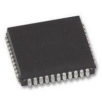
MCU 8BIT 80C51 16K FLASH, PLCC44
Manufacturer
NXP Semiconductors
Datasheet
1.P89V51RC2FBC557.pdf
(80 pages)
Specifications of P89V51RB2FA
Controller Family/series
(8051) 8052
Core Size
8bit
No. Of I/o's
32
Program Memory Size
16KB
Ram Memory Size
1KB
Cpu Speed
40MHz
Oscillator Type
External Only
No. Of Timers
4
No. Of Pwm
RoHS Compliant
Available stocks
Company
Part Number
Manufacturer
Quantity
Price
Company:

Part Number:
P89V51RB2FA
Manufacturer:
NXP
Quantity:
1 000
Company:
Part Number:
P89V51RB2FA
Manufacturer:
NXP
Quantity:
2 000
Part Number:
P89V51RB2FA
Manufacturer:
NXP/恩智浦
Quantity:
20 000
Part Number:
P89V51RB2FA (FLA
Manufacturer:
NXP/恩智浦
Quantity:
20 000
Company:
Part Number:
P89V51RB2FA,529
Manufacturer:
NXP Semiconductors
Quantity:
10 000
Company:
Part Number:
P89V51RB2FAЈ¬529
Manufacturer:
NXP
Quantity:
150


NXP Semiconductors
P89V51RB2_RC2_RD2_5
Product data sheet
6.4 Timers/counters 0 and 1
Table 13.
The two 16-bit Timer/counter registers: Timer 0 and Timer 1 can be configured to operate
either as timers or event counters (see
In the ‘Timer’ function, the register is incremented every machine cycle. Thus, one can
think of it as counting machine cycles. Since a machine cycle consists of six oscillator
periods, the count rate is
In the ‘Counter’ function, the register is incremented in response to a 1-to-0 transition at its
corresponding external input pin, T0 or T1. In this function, the external input is sampled
once every machine cycle.
When the samples show a high in one cycle and a low in the next cycle, the count is
incremented. The new count value appears in the register in the machine cycle following
the one in which the transition was detected. Since it takes two machine cycles (12
oscillator periods) for 1-to-0 transition to be recognized, the maximum count rate is
the oscillator frequency. There are no restrictions on the duty cycle of the external input
signal, but to ensure that a given level is sampled at least once before it changes, it should
be held for at least one full machine cycle. In addition to the ‘Timer’ or ‘Counter’ selection,
Timer 0 and Timer 1 have four operating modes from which to select.
The ‘Timer’ or ‘Counter’ function is selected by control bits C/T in the Special Function
Register TMOD. These two Timer/counters have four operating modes, which are
selected by bit-pairs (M1, M0) in TMOD. Modes 0, 1, and 2 are the same for both
Timers/counters. Mode 3 is different. The four operating modes are described in the
following text.
IAP function
Program Security Bit, Double
Clock
Read Security Bit, Double Clock,
SoftICE
Erase sector
IAP function calls
Rev. 05 — 12 November 2009
1
6
of the oscillator frequency.
…continued
IAP call parameters
Input parameters:
R1 = 05H
DPL = 01H = security bit
DPL = 05H = Double Clock
Return parameter(s):
ACC = 00 = pass
ACC = !00 = fail
Input parameters:
ACC = 07H
Return parameter(s):
ACC = 00 SoftICE S/N-match 0 SB 0 DBL_CLK
Input parameters:
R1 = 08H
DPH = sector address high byte
DPL = sector address low byte
Return parameter(s):
ACC = 00 = pass
ACC = !00 = fail
Table 14
P89V51RB2/RC2/RD2
and
8-bit microcontrollers with 80C51 core
Table
15).
© NXP B.V. 2009. All rights reserved.
27 of 80
1
12
of
Related parts for P89V51RB2FA
Image
Part Number
Description
Manufacturer
Datasheet
Request
R

Part Number:
Description:
NXP Semiconductors designed the LPC2420/2460 microcontroller around a 16-bit/32-bitARM7TDMI-S CPU core with real-time debug interfaces that include both JTAG andembedded trace
Manufacturer:
NXP Semiconductors
Datasheet:

Part Number:
Description:
NXP Semiconductors designed the LPC2458 microcontroller around a 16-bit/32-bitARM7TDMI-S CPU core with real-time debug interfaces that include both JTAG andembedded trace
Manufacturer:
NXP Semiconductors
Datasheet:
Part Number:
Description:
NXP Semiconductors designed the LPC2468 microcontroller around a 16-bit/32-bitARM7TDMI-S CPU core with real-time debug interfaces that include both JTAG andembedded trace
Manufacturer:
NXP Semiconductors
Datasheet:
Part Number:
Description:
NXP Semiconductors designed the LPC2470 microcontroller, powered by theARM7TDMI-S core, to be a highly integrated microcontroller for a wide range ofapplications that require advanced communications and high quality graphic displays
Manufacturer:
NXP Semiconductors
Datasheet:
Part Number:
Description:
NXP Semiconductors designed the LPC2478 microcontroller, powered by theARM7TDMI-S core, to be a highly integrated microcontroller for a wide range ofapplications that require advanced communications and high quality graphic displays
Manufacturer:
NXP Semiconductors
Datasheet:
Part Number:
Description:
The Philips Semiconductors XA (eXtended Architecture) family of 16-bit single-chip microcontrollers is powerful enough to easily handle the requirements of high performance embedded applications, yet inexpensive enough to compete in the market for hi
Manufacturer:
NXP Semiconductors
Datasheet:
Part Number:
Description:
The XA-S3 device is a member of Philips Semiconductors? XA(eXtended Architecture) family of high performance 16-bitsingle-chip microcontrollers
Manufacturer:
NXP Semiconductors
Datasheet:

Part Number:
Description:
The NXP BlueStreak LH75401/LH75411 family consists of two low-cost 16/32-bit System-on-Chip (SoC) devices
Manufacturer:
NXP Semiconductors
Datasheet:
Part Number:
Description:
The NXP LPC3130/3131 combine an 180 MHz ARM926EJ-S CPU core, high-speed USB2
Manufacturer:
NXP Semiconductors
Datasheet:
Part Number:
Description:
The NXP LPC3141 combine a 270 MHz ARM926EJ-S CPU core, High-speed USB 2
Manufacturer:
NXP Semiconductors
Part Number:
Description:
The NXP LPC3143 combine a 270 MHz ARM926EJ-S CPU core, High-speed USB 2
Manufacturer:
NXP Semiconductors

Part Number:
Description:
The NXP LPC3152 combines an 180 MHz ARM926EJ-S CPU core, High-speed USB 2
Manufacturer:
NXP Semiconductors
Part Number:
Description:
The NXP LPC3154 combines an 180 MHz ARM926EJ-S CPU core, High-speed USB 2
Manufacturer:
NXP Semiconductors

Part Number:
Description:
Standard level N-channel enhancement mode Field-Effect Transistor (FET) in a plastic package using NXP High-Performance Automotive (HPA) TrenchMOS technology
Manufacturer:
NXP Semiconductors
Datasheet: