XTOB004CC1 EATON CUTLER HAMMER, XTOB004CC1 Datasheet - Page 218
XTOB004CC1
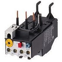
Manufacturer Part Number
XTOB004CC1
Description
Overload Relay
Manufacturer
EATON CUTLER HAMMER
Datasheet
1.XTCE007B10A.pdf
(312 pages)
Specifications of XTOB004CC1
Overload Adjustment Current Min
2.4A
Overload Adjustment Current Max
4A
Coil Voltage Dc Max
220V
Contactor Direction
Non Reversing
Coil Voltage Vdc Nom
220V
Lead Free Status / RoHS Status
Lead free / RoHS Compliant


34-218
34
The following are important criteria for
selecting switchgear suitable for export:
■
■
■
■
For motor-protective circuit-breakers
Use inherently short-circuit proof
switches capable of controlling the
highest prospective fault levels at
the point of installation without the
need for back-up protection.
❑
For circuit-breakers
Use types with visible contacts,
quick-make and quick-break
operation as standard. Use current-
limiting circuit-breakers for high
short-circuit levels. Selective
switches are recommended for the
selective graduation of networks.
❑
For contactors
Use contactors whose entire range
provides consistently reliable opera-
tion in the event of voltage drops
(consistently down to 80% U n
should be aimed for) and whose
contact system will not assume
an indeterminate position either
on closing or on opening in such
conditions.
❑
For enclosures
Use insulated enclosures with
transparent covers (i.e. “totally
insulated” enclosures).
IEC Contactors & Starters
XT IEC Power Control
Reference Data
Advantage:
– No restrictions whatsoever for
– Complete independence from
– No problems getting spare
Advantage:
– Independence from local
– The effects of short-circuits are
– Fuseless installations offer
Advantage:
– During the electrification work
installation
the on-site protective system
parts
accident prevention regulations
requiring visible contacts, and
safety faults caused by inexpe-
rienced operating personnel.
kept to a minimum.
greater safety and reliability in
plant operation. In the event of
a fault, only the faulty section
of the system is isolated.
in areas such as Africa and the
Middle East, an insufficient
voltage stability is — at least
for a certain time — likely in
many applications (for example
due to long spur lines or small
local generators). The use of
devices that fulfill the above
requirements will eliminate one
of the main failure causes
related to contactors.
■
For more information visit: www.eaton.com
❑
For overcurrent protective devices
Always use circuit-breakers and
motor-protective circuit-breakers.
Avoid fuses as far as possible.
❑
Advantage:
– Total insulation is the best pos-
– Insulated enclosures com-
Advantage:
– The operational reliability of a
sible protective measure from
the user’s point of view, avoid-
ing reliance on the possibly
doubtful skills of unknown
installation personnel. Further-
more, protective measures
based on earthing are often
extremely difficult, if not
impossible (in the Middle East,
for example, due to the dryness
of the ground).
pletely eliminate the need for
any additional protection
against corrosion. The trans-
parent covers contribute
significantly to the correct
operation of a system, because
switchgear operation can be
monitored even with the doors
or covers closed, thus virtually
eliminating the possibility of
these being left open through
carelessness. The transparent
cover is an important contribu-
tion to safety, especially where
exports to areas of uncertain
skills are concerned.
system is especially important
for export contracts. Circuit-
breakers and motor-protective
circuit-breakers provide this
reliability in full measure since
they can be immediately
reclosed once a fault has been
cleared, they disconnect all
poles, they have ideal protec-
tion through high tripping
accuracy and they can be used
for selective operation.
Because they have no fuses or
other consumables, they also
greatly reduce the problem of
obtaining replacement parts.
The advantages of fuseless
design for export are especially
evident in this case. No compli-
cated investigation is needed to
find out which fusing system is
used in the respective location
and which specifications have
to be followed to select the cor-
rect fuses. Often several differ-
ent fuse systems with widely
varying characteristics are used
side-by-side in the same coun-
try. For the uninitiated, it may
be almost impossible to find
■
Test Authorities
USA
USA
UL
Canada
CDN
CSA
Romania
RO
ICECON
Russia
RUS
GOST-R
South Africa
ZA
SABS
Slovakia
SK
SKTC
Poland
PL
BBJ-SEP
Turkey
TR
TSE
China
PRC
CCC
Ukraine
UA
Ukrain-GOST
For main switches and safety
switches
Use devices with positive contact
separation and clear switch
position indication.
❑
Advantage:
– The mechanical coupling of the
the right fuse in these circum-
stances. These problems do
not arise where a circuit-
breaker is used.
actuating element with the
contacts ensues that the OFF
position is indicated only when
all main contacts are separated
by the prescribed distance, and
only in this position can the
switch be padlocked. This
ensures safety when carrying
out maintenance and repair
work on the installation or
machinery.
CA08102001E
March 2009
Related parts for XTOB004CC1
Image
Part Number
Description
Manufacturer
Datasheet
Request
R

Part Number:
Description:
PROGRAMMABLE LOGIC CONTROLLER
Manufacturer:
EATON CUTLER HAMMER
Part Number:
Description:
Pm Power Pro 3000/5000 A-B Accel/On Interface
Manufacturer:
EATON CUTLER HAMMER
Part Number:
Description:
Handle Tie Bar For (2) - 1 Pole Type BR Breakers
Manufacturer:
EATON CUTLER HAMMER
Part Number:
Description:
Type CH Breaker 150A/2 Pole 120/240V 10K
Manufacturer:
EATON CUTLER HAMMER
Part Number:
Description:
Tenant Branch Breaker 125A/3 Pole 120/240V 42K
Manufacturer:
EATON CUTLER HAMMER
Part Number:
Description:
Type CL Breaker 25A/1Pole 120/240V 10K-Classified 1" Ckt Bkr
Manufacturer:
EATON CUTLER HAMMER
Part Number:
Description:
FD BREAKER 1P 80 AMP WITH LOAD ONLY TERMINALS
Manufacturer:
EATON CUTLER HAMMER
Part Number:
Description:
GD 2 POLE BREAKER, 25 AMP, SINGLE PACKED
Manufacturer:
EATON CUTLER HAMMER
Part Number:
Description:
Handle Tie Bar For (2) - 1 Pole Type BR Breakers
Manufacturer:
EATON CUTLER HAMMER
Part Number:
Description:
Type CL Breaker 25A/1Pole 120/240V 10K-Classified 1" Ckt Bkr
Manufacturer:
EATON CUTLER HAMMER