XTOB004CC1 EATON CUTLER HAMMER, XTOB004CC1 Datasheet - Page 241
XTOB004CC1
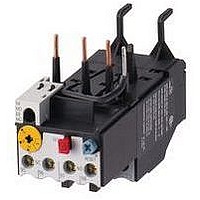
Manufacturer Part Number
XTOB004CC1
Description
Overload Relay
Manufacturer
EATON CUTLER HAMMER
Datasheet
1.XTCE007B10A.pdf
(312 pages)
Specifications of XTOB004CC1
Overload Adjustment Current Min
2.4A
Overload Adjustment Current Max
4A
Coil Voltage Dc Max
220V
Contactor Direction
Non Reversing
Coil Voltage Vdc Nom
220V
Lead Free Status / RoHS Status
Lead free / RoHS Compliant


March 2009
Table 34-278. Specifications (Continued)
Finger Protection
Terminals L1, L2, L3/T1, T2, T3
Operation Performance
Control Terminals
Temperature
CA08102001E
Description
Front
At Terminals
At Terminals with
max. size wire
installed
1 Wire per Terminal
(stranded or solid)
2 Wires per Terminal
(stranded or solid)
Strip Length
Torque (max.)
Driver
Coil Voltage (nominal) 24V DC
Coil Operating
Voltage Range (VDC)
(- and +)
1 Wire per Terminal
(- and +)
2 Wires per Terminal
(P, F, R, 1, 2, 3)
1 Wire per Terminal
(P, F, R, 1, 2, 3)
2 Wires per Terminal
Torque (max.)
Strip Length
Driver (Flat)
Operating
Storage
Flat
Hex Key
Use Class B 75°C copper wire only (or 90°C
copper wire sized for 75°C operation per NEC).
Not applicable to starter T1, T2, T3. One wire per terminal.
27 mm Non-reversing Starter —
• (- and +) 14 AWG (1.5 mm
• P, F, 1, A: 1 wire per terminal only,
• Torque: 2.25 lb-in (.25 Nm)
• Driver: .09 in (2.5 mm)
Consult factory for higher ratings.
22 – 14 AWG (0.5 – 1.5 mm
A-Frame
27 mm
IP20
IP20
IP20
16 – 12 AWG
(1.5 – 2.5 mm
16 – 12 AWG
(1.5 – 2.5 mm
.32" (8 mm)
18 lb-in (2.0
Nm)
PZ1 or 3/16"
—
20 – 28
14 – 12 AWG
(1.5 – 2.5 mm
14 AWG
(1.5 mm
22 – 12 AWG
(0.5 – 2.5 mm
18 – 14 AWG
(0.75 – 1.5 mm
4.5 lb-in (.5 Nm) 4.5 lb-in (.5 Nm)
.25 (7 mm)
.13 (3.5 mm)
-40° to +149°F
(-40° to +65°C)
-58° to +176°F
(-50° to +80°C)
2
2
) only
2
)
)
2
2
2
2
)
)
)
)
2
)
IP20
B-Frame
45 mm
IP20
IP10
14 – 8 AWG
(1.5 – 10 mm
14 – 10 AWG
(1.5 – 4 mm
.45" (11 mm)
20 lb-in (2.2 Nm) for
14 – 10 AWG
(1.5 – 6 mm
25 lb-in (2.8 Nm) for
8 AWG (10 mm
—
2.5 mm
24V DC
20 – 28
14 – 12 AWG
(1.5 – 2.5 mm
14 AWG
(1.5 mm
22 – 12 AWG
(0.5 – 2.5 mm
18 – 14 AWG
(0.75 – 1.5 mm
.25 (7 mm)
.13 (3.5 mm)
-40° to +149°F
(-40° to +65°C)
-58° to +176°F
(-50° to +80°C)
2
)
2
2
)
);
2
2
2
)
For more information visit: www.eaton.com
)
)
2
2
)
)
IEC Contactors & Starters
IT. Electro-Mechanical
Technical Data and Specifications
C-Frame
54 mm
IP20
IP10
IP10
14 – 4 AWG
(1.5 – 16 mm
14 – 6 AWG
(1.5 – 16 mm
.5" (12 mm)
35 lb-in (4.0 Nm) for
14 – 10 AWG (1.5 – 6
mm
40 lb-in (4.5 Nm) for
8 AWG (10 mm
45 lb-in (5.0 Nm) for
6 – 4 AWG (16 mm
—
3 mm
24V DC
20 – 28
14 – 12 AWG
(1.5 – 2.5 mm
14 AWG
(1.5 mm
22 – 12 AWG
(0.5 – 2.5 mm
18 – 14 AWG
(0.75 – 1.5 mm
4.5 lb-in (.5 Nm)
.25 (7 mm)
.13 (3.5 mm)
-40° to +149°F
(-40° to +65°C)
-58° to +176°F
(-50° to +80°C)
2
);
2
)
2
2
2
2
)
)
)
)
2
2
)
);
2
)
D-Frame
76 mm
IP20
IP00
IP10
14 – 1 AWG
(1.5 – 35 mm
14 – 2 AWG
(1.5 – 25 mm
.7" (18 mm)
45 lb-in (5.0 Nm) for Single
14 – 8 AWG (1.5 – 10 mm
100 lb-in (11 Nm) for Single
6 – 1 AWG (16 – 35 mm
and Dual Wire Combina-
tions
—
4 mm [5/32"]
24V DC
20 – 28
14 – 12 AWG
(1.5 – 2.5 mm
14 AWG
(1.5 mm
22 – 12 AWG
(0.5 – 2.5 mm
18 – 14 AWG
(0.75 – 1.5 mm
4.5 lb-in (.5 Nm)
.25 (7 mm)
.13 (3.5 mm)
-40° to +149°F
(-40° to +65°C)
-58° to +176°F
(-50° to +80°C)
2
)
2
2
2
2
)
)
)
)
2
)
2
)
2
);
E-Frame
105 mm
IP20
IP00
IP00
6 – 250 MCM
(16 – 120 mm
6 – 3/0 AWG
(16 – 70 mm
.8" (21 mm)
250 lb-in
(28 Nm)
—
8 mm [5/16"]
24V DC
20 – 28
14 – 12 AWG
(1.5 – 2.5 mm
14 AWG
(1.5 mm
22 – 12 AWG
(0.5 – 2.5 mm
18 – 14 AWG
(0.75 – 1.5 mm
4.5 lb-in (.5 Nm) 4.5 lb-in (.5 Nm)
.25 (7 mm)
.13 (3.5 mm)
-40° to +149°F
(-40° to +65°C)
-58° to +176°F
(-50° to +80°C)
2
)
2
2
)
2
2
)
)
)
2
)
F-Frame
140 mm
IP00
IP00
IP00
4 – 750 MCM
(25 – 420 mm
1/0 – 300 MCM
(50 – 150 mm
1.5" (40 mm)
550 lb-in
(62 Nm)
—
8 mm [5/16"]
24V DC
20 – 28
14 – 12 AWG
(1.5 – 2.5 mm
14 AWG
(1.5 mm
22 – 12 AWG
(0.5 – 2.5 mm
18 – 14 AWG
(0.75 – 1.5 mm
.25 (7 mm)
.13 (3.5 mm)
-40° to +149°F
(-40° to +65°C)
-58° to +176°F
(-50° to +80°C)
2
)
34-241
2
2
2
2
)
)
)
)
2
)
34
Related parts for XTOB004CC1
Image
Part Number
Description
Manufacturer
Datasheet
Request
R

Part Number:
Description:
PROGRAMMABLE LOGIC CONTROLLER
Manufacturer:
EATON CUTLER HAMMER
Part Number:
Description:
Pm Power Pro 3000/5000 A-B Accel/On Interface
Manufacturer:
EATON CUTLER HAMMER
Part Number:
Description:
Handle Tie Bar For (2) - 1 Pole Type BR Breakers
Manufacturer:
EATON CUTLER HAMMER
Part Number:
Description:
Type CH Breaker 150A/2 Pole 120/240V 10K
Manufacturer:
EATON CUTLER HAMMER
Part Number:
Description:
Tenant Branch Breaker 125A/3 Pole 120/240V 42K
Manufacturer:
EATON CUTLER HAMMER
Part Number:
Description:
Type CL Breaker 25A/1Pole 120/240V 10K-Classified 1" Ckt Bkr
Manufacturer:
EATON CUTLER HAMMER
Part Number:
Description:
FD BREAKER 1P 80 AMP WITH LOAD ONLY TERMINALS
Manufacturer:
EATON CUTLER HAMMER
Part Number:
Description:
GD 2 POLE BREAKER, 25 AMP, SINGLE PACKED
Manufacturer:
EATON CUTLER HAMMER
Part Number:
Description:
Handle Tie Bar For (2) - 1 Pole Type BR Breakers
Manufacturer:
EATON CUTLER HAMMER
Part Number:
Description:
Type CL Breaker 25A/1Pole 120/240V 10K-Classified 1" Ckt Bkr
Manufacturer:
EATON CUTLER HAMMER