XTOB004CC1 EATON CUTLER HAMMER, XTOB004CC1 Datasheet - Page 246
XTOB004CC1
Manufacturer Part Number
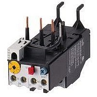
XTOB004CC1
Description
Overload Relay
Manufacturer
EATON CUTLER HAMMER
Datasheet
1.XTCE007B10A.pdf
(312 pages)
Specifications of XTOB004CC1
Overload Adjustment Current Min
2.4A
Overload Adjustment Current Max
4A
Coil Voltage Dc Max
220V
Contactor Direction
Non Reversing
Coil Voltage Vdc Nom
220V
Lead Free Status / RoHS Status
Lead free / RoHS Compliant


34-246
34
Auxiliary Contacts
Table 34-284. Auxiliary Contact Availability — A – F Frames
Figure 34-153. Connecting Diagram — A – F Frames
Table 34-285. Auxiliary Contact Availability — F-Frame 140 mm
Note:
■
■
■
■
Front Mounted (Maximum Auxiliaries per Contactor/Starter)
Contactor/Starter Size
A-Frame
27 mm
1
1
—
—
—
1
Auxiliary Contacts per Non-reversing and Reversing Contactor or Starter
Max. Contact
2
2
6
2
6
2
2
2
3
Side Mounted: Maximum (10) total circuits.
Front Mounted: Maximum (6) total circuits.
Maximum 4 auxiliaries per side (base + 3 side mounted).
EMASA/B_ have been superseded by the above Catalog Numbers.
EMA13
Other combinations: “Single, dual, single”; “Dual, single, dual”; “Dual, logic level, dual”.
For reversers, multiply quantities by two.
Form C Contacts.
For reversers, multiply quantities by two.
NO
IEC Contactors & Starters
IT. Electro-Mechanical
Accessories
3
4
Type
1NO
1NO-1NC
1NO
1NO
Logic Level
1NC
1NC
Logic Level
1NO-1NC
1NO-1NC
Logic Level
1NO-1NC
Logic Level
B-Frame
45 mm
3
3
2
2
2
2
NC
2
1
EMA14
C-Frame
54 mm
3
3
2
2
2
3
Description
Base auxiliary (max. 1 per side)
Base auxiliary (max. 1 per side)
C320KGS41 or C320KGS42 required
(max. 3 Add-on auxiliaries per side)
C320KGS41 or C320KGS42 required
(max. 1 Add-on auxiliary per side)
C320KGS41 or C320KGS42 required
(max. 2 Add-on auxiliaries per side)
C320KGS41 or C320KGS42 required
(max. 1 Add-on auxiliary per side)
C320KGS41 or C320KGS42 required
(max. 1 Add-on auxiliary per side)
C320KGS41 or C320KGS42 required
(max. 1 Add-on auxiliary per side)
Front Mounted Only
NO
13
14
EMA15
D-Frame
76 mm
3
3
3
3
3
3
21
NC
22
E-Frame
105 mm
3
3
3
3
3
3
NO
14
13
EMA16
Auxiliary Contacts are available for
mounting on IT. Electro-Mechanical
Contactors and Starters. The various
choices available for non-reversing
models are shown in Tables 34-284
and 34-285, and their ratings in Tables
34-286 – 34-288. For reversing models,
the number of auxiliaries indicated is
for each of the contactors/starters in
the assembly.
For more information visit: www.eaton.com
F-Frame
140 mm
—
—
—
—
—
3
23
NO
24
NC
12
11
Catalog
Number
C320KGS41
C320KGS42
C320KGS20
C320KGS20L
C320KGS21
C320KGS21L
C320KGS22
C320KGS22L
EMA70
Contact
Type
1NO
1NC
1NO-1NC
2NO
2NC
Logic Level
1NO-1NC
EMA17
21
NC
22
Catalog
Number
EMA13
EMA14
EMA15
EMA16
EMA17
EMA70
NO
4
1
Common
Price
U.S. $
EMA70
Price
U.S. $
2
NC
1
Table 34-286. IEC Ratings
Table 34-287. NEMA A600 Ratings
Table 34-288. NEMA P300 Ratings
Table 34-289. EMA70 Auxiliary Contact
Starter Network Adapter Product
(SNAP)
The Starter Network Adapter Product
(SNAP) is a front-mount device that
serves as a single DeviceNet node, pro-
viding communication capability, control
and monitoring to Eaton’s Cutler-Ham-
mer Intelligent Technologies (IT.) Electro-
mechanical Starters (B – F Frames) as
well as the IT. S75X SoftStart.
When HAND-OFF-AUTO is required,
the HOA option will allow for the con-
nection of hard wired operators. This
option allows for Hand Control even if
the DSNAP is not connected.
For more information and pricing, see
Tab 50.
Discount Symbol . . . . . . . . . . . . . . . . . . . . . . . . 1CD1
DC-13
U
Voltage
125
250
Current
Make and
Interrupting
Break
Continuous
Thermal
Current
Make and
Interrupting
Break
Continuous
Thermal
DC-12
Ue
30
24
48
e
Ie
.1
l
Amps.
5
2.5
1.1
e
.55
Cat. No. D77B-DSNAP-X1
with 54 mm IT. Starter
AC Voltage
120
60
10
10
DC Voltage
125
1.1
1.1
5
5
6
AC-15
U
Voltage
120
240
440
AC-12
Ue
250
48
e
240
30
10
10
3
480
15
10
10
250
5
5
CA08102001E
1.5
.55
.55
March 2009
Ie
.1
l
Amps.
8
6
4
2
e
600
12
10
10
1.2
Related parts for XTOB004CC1
Image
Part Number
Description
Manufacturer
Datasheet
Request
R

Part Number:
Description:
PROGRAMMABLE LOGIC CONTROLLER
Manufacturer:
EATON CUTLER HAMMER
Part Number:
Description:
Pm Power Pro 3000/5000 A-B Accel/On Interface
Manufacturer:
EATON CUTLER HAMMER
Part Number:
Description:
Handle Tie Bar For (2) - 1 Pole Type BR Breakers
Manufacturer:
EATON CUTLER HAMMER
Part Number:
Description:
Type CH Breaker 150A/2 Pole 120/240V 10K
Manufacturer:
EATON CUTLER HAMMER
Part Number:
Description:
Tenant Branch Breaker 125A/3 Pole 120/240V 42K
Manufacturer:
EATON CUTLER HAMMER
Part Number:
Description:
Type CL Breaker 25A/1Pole 120/240V 10K-Classified 1" Ckt Bkr
Manufacturer:
EATON CUTLER HAMMER
Part Number:
Description:
FD BREAKER 1P 80 AMP WITH LOAD ONLY TERMINALS
Manufacturer:
EATON CUTLER HAMMER
Part Number:
Description:
GD 2 POLE BREAKER, 25 AMP, SINGLE PACKED
Manufacturer:
EATON CUTLER HAMMER
Part Number:
Description:
Handle Tie Bar For (2) - 1 Pole Type BR Breakers
Manufacturer:
EATON CUTLER HAMMER
Part Number:
Description:
Type CL Breaker 25A/1Pole 120/240V 10K-Classified 1" Ckt Bkr
Manufacturer:
EATON CUTLER HAMMER