CDB3318 Cirrus Logic Inc, CDB3318 Datasheet - Page 37
CDB3318
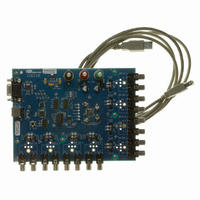
Manufacturer Part Number
CDB3318
Description
Eval Bd - 8-channel Digital Vol Cntrl
Manufacturer
Cirrus Logic Inc
Specifications of CDB3318
Main Purpose
Audio, Volume Control
Embedded
No
Utilized Ic / Part
CS3318
Primary Attributes
8 Single-Ended Analog Inputs and Outputs, USB or RS232 Interface
Secondary Attributes
Graphical User Interface
Description/function
Audio DSPs
Operating Supply Voltage
8 V to 9 V
Product
Audio Modules
Lead Free Status / RoHS Status
Contains lead / RoHS non-compliant
For Use With/related Products
CS3310
Lead Free Status / RoHS Status
Contains lead / RoHS non-compliant, Contains lead / RoHS non-compliant
Other names
598-1497


DS693F1
7.11
7.11.1 Master 1 Mute (Bit 1)
7.11.2 Master 1 ¼ dB Control (Bit 0)
7.12
7.13
7.13.1 Master 2 Volume Control (Bits 7:0)
M2_Ch8M
Reserved
M2_Vol7
7
7
7
Master 1 Control - Address 12h
Master 2 Mask - Address 13h
Master 2 Volume - Address 14h
Default = 0
Function:
Default = 0
Function:
Each bit in this register serves as a Master 2 mask for its corresponding channel.
If a mask bit is set to ‘1’, the corresponding channel is unmasked, meaning that it will be affected by the
Master 2 volume and muting controls.
If a mask bit is set to ‘0’, the corresponding channel is masked, meaning that it will not be affected by the
Master 2 volume and muting controls.
This register defaults to FFh (all channels unmasked).
Default = 11010010
Function:
This bit controls the Master 1 mute state. When set, the Master 1 mute condition is active. When
cleared, the Master 1 mute condition is released.
See
When set, ¼ dB of gain will be added to the Master 1 volume level.
See
The Master 2 volume control register allows the user to simultaneously gain or attenuate all un-
masked channels from +22 dB to -96 dB in 0.5 dB increments. The volume changes are implemented
as dictated by the ZCMode[1:0] and TimeOut[2:0] bits in the Device Config 2 register (see
Configuration 2 - Address 0Ch” on page
The value of the Master 2 volume control register is mapped to the desired 0.5 dB step Master 2 vol-
ume setting by the following equation:
M2_Ch7M
Reserved
M2_Vol6
“Muting Controls” on page 21
Table 6 on page 32
6
6
6
M2_Ch6M
Reserved
M2_Vol5
Register Value
5
5
5
for an example of volume settings using the ¼ dB control.
M2_Ch5M
Reserved
M2_Vol4
for more information about the muting behavior of the CS3318.
=
4
4
4
(
2
×
34).
Desired Volume Setting in dB
M2_Ch4M
Reserved
M2_Vol3
3
3
3
M2_Ch3M
Reserved
M2_Vol2
2
2
2
)
+
M2_Ch2M
M1_Mute
M2_Vol1
210
1
1
1
M2_Ch1M
CS3318
M2_Vol0
M1_Qtr
“Device
0
0
0
37
Related parts for CDB3318
Image
Part Number
Description
Manufacturer
Datasheet
Request
R

Part Number:
Description:
Development Kit
Manufacturer:
Cirrus Logic Inc
Datasheet:
Part Number:
Description:
Development Kit
Manufacturer:
Cirrus Logic Inc
Datasheet:


Part Number:
Description:
High-efficiency PFC + Fluorescent Lamp Driver Reference Design
Manufacturer:
Cirrus Logic Inc
Datasheet:
Part Number:
Description:
Development Kit
Manufacturer:
Cirrus Logic Inc
Datasheet:
Part Number:
Description:
Development Kit
Manufacturer:
Cirrus Logic Inc
Datasheet:

Part Number:
Description:
Development Kit
Manufacturer:
Cirrus Logic Inc
Datasheet:
Part Number:
Description:
Development Kit
Manufacturer:
Cirrus Logic Inc
Datasheet:
Part Number:
Description:
Development Kit
Manufacturer:
Cirrus Logic Inc
Datasheet:
Part Number:
Description:
Development Kit
Manufacturer:
Cirrus Logic Inc
Datasheet:

Part Number:
Description:
EVALUATION BOARD FOR CS8427
Manufacturer:
Cirrus Logic Inc
Datasheet:

Part Number:
Description:
BOARD EVAL FOR CS8416 RCVR
Manufacturer:
Cirrus Logic Inc
Datasheet:

Part Number:
Description:
EVALUATION BOARD FOR CS8420
Manufacturer:
Cirrus Logic Inc
Datasheet:

Part Number:
Description:
KIT DEVELOPMENT EP9315 ARM9
Manufacturer:
Cirrus Logic Inc
Datasheet:

Part Number:
Description:
KIT DEVELOPMENT EP9302 ARM9
Manufacturer:
Cirrus Logic Inc
Datasheet: