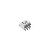
MOC213R2M Fairchild Semiconductor, MOC213R2M Datasheet - Page 5

MOC213R2M
Manufacturer Part Number
MOC213R2M
Description
Transistor Output Optocouplers SO-8 PHOTO TRANS T/R
Manufacturer
Fairchild Semiconductor
Datasheet
1.MOC213M.pdf
(10 pages)
Specifications of MOC213R2M
Maximum Input Diode Current
60 mA
Maximum Reverse Diode Voltage
6 V
Output Device
Phototransistor
Output Type
DC
Configuration
1 Channel
Input Type
DC
Maximum Collector Emitter Voltage
30 V
Maximum Collector Emitter Saturation Voltage
0.4 V
Isolation Voltage
2500 Vrms
Maximum Forward Diode Voltage
1.5 V
Maximum Collector Current
150 mA
Maximum Power Dissipation
250 mW
Maximum Operating Temperature
+ 100 C
Minimum Operating Temperature
- 40 C
Package / Case
SOIC-8 Narrow
Number Of Elements
1
Reverse Breakdown Voltage
6V
Forward Voltage
1.5V
Forward Current
60mA
Collector-emitter Voltage
30V
Package Type
SOIC W
Collector Current (dc) (max)
150mA
Power Dissipation
250mW
Collector-emitter Saturation Voltage
0.4V
Pin Count
8
Mounting
Surface Mount
Operating Temp Range
-40C to 100C
Operating Temperature Classification
Industrial
Lead Free Status / RoHS Status
Lead free / RoHS Compliant
Other names
MOC213R2M_NL
Available stocks
Company
Part Number
Manufacturer
Quantity
Price
Company:
Part Number:
MOC213R2M
Manufacturer:
FAIRCHIL
Quantity:
7 812
Part Number:
MOC213R2M
Manufacturer:
FAIRCHILD/仙童
Quantity:
20 000
©2005 Fairchild Semiconductor Corporation
MOC211M, MOC212M, MOC213M Rev. 1.0.1
Typical Performance Curves
INPUT
1.0
0.9
0.8
0.7
0.6
0.5
0.4
0.3
0.2
0.1
0.0
10
I
F
I
F
= 20mA
TEST CIRCUIT
Fig. 7 CTR vs. R BE (Saturated)
R
R
BE
BE
–
BASE RESISTANCE (k )
100
I
V
C
Figure 10. Switching Time Test Circuit and Waveforms
V
Normalized to:
CTR at R
CC
CE
= 0.3V, T
= 10V
1.6
1.4
1.2
1.0
0.8
0.6
0.4
0.2
0.0
I
OUTPUT
I
F
R
F
0.01
BE
= 10mA
= 5mA
L
Adjust I
= Open
V
I
R
NORMALIZED TO :
t
C
of f f
A
CC
L
= 2mA
= 25 C
(Continued)
= 100
AT R
= 10V
BE
F
to produce I
= OPEN
R
Fig. 9 Normalized t off vs. R BE
0.1
BE
1000
– BASE RESISTANCE
C
= 2mA
5
1
4.0
3.5
3.0
2.5
2.0
1.5
1.0
0.5
0.0
0.01
(M )
10%
90%
10
V
I
R
NORMALIZED TO :
t
C
on
CC
L
= 2mA
= 100
AT R
t
on
= 10V
BE
WAVEFORMS
= OPEN
R
Fig. 8 Normalized t on vs. R BE
0.1
BE
100
–
BASE RESISTANCE (M )
t
r
1
t
t
f
off
INPUT PULSE
OUTPUT PULSE
10
www.fairchildsemi.com
100


