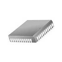
TMC2242AR2C1 Fairchild Semiconductor, TMC2242AR2C1 Datasheet - Page 2

TMC2242AR2C1
Manufacturer Part Number
TMC2242AR2C1
Description
Video ICs Interp/Decim Filter Digital HB 12B/16B
Manufacturer
Fairchild Semiconductor
Type
Digital Half Band Filtersr
Datasheet
1.TMC2242AR2C1.pdf
(16 pages)
Specifications of TMC2242AR2C1
Operating Supply Voltage
- 0.5 V to + 7 V
Supply Current
195 mA
Maximum Operating Temperature
70 C
Package / Case
PLCC-44
Minimum Operating Temperature
0 C
Mounting Style
SMD/SMT
Lead Free Status / RoHS Status
Lead free / RoHS Compliant
PRODUCT SPECIFICATION
Description
The filter response is flat to within ± 0.01 dB from 0.00 to
0.22 x f
from 0.28 x f
down at 0.25 x f
TMC2242A and TMC2242B have linear phase response.
Full compliance with the CCIR-601 standard of 12 dB atten-
uation at 0.25 x f
The TMC2242A and TMC2242B are fabricated on an
advanced submicron CMOS process. They are available in a
44-lead J-lead PLCC package. Performance is guaranteed
from 0 ° C to 70 ° C.
Functional Description
The TMC2242A and TMC2242B implement a fixed-coeffi-
cient linear-phase Finite Impulse Response (FIR) filter of 55
effective taps, with special rate-matching input and output
structures to facilitate 2:1 decimation and 1:2 interpolation.
The faster of either the input or output registers will operate
at the guaranteed maximum clock rate (speed grade). The
total internal pipeline latency from the input of an impulse to
the corresponding output peak (digital group delay) is 34
cycles; the 55-value output response begins after 7 clock
cycles and ends after 61 cycles.
To perform interpolation, the chip slows the effective input
register clock rate to half the output rate. It internally inserts
zeroes between the incoming data samples to "pad" the input
data rate to match the output rate.
Pin Assignments
2
SO
SO
SO
GND
SO
SO
V
SO
SO
SO
SO
DD
12
11
10
9
8
7
6
5
4
s
, with stopband attenuation greater than 59.4 dB
7
8
9
10
11
12
13
14
15
16
17
s
to the Nyquist frequency. The response is 6 dB
s
s
. Symmetric-coefficient filters such as the
is achieved by cascading two parts.
(continued)
44 Lead PLCC
TMC2242A
TMC2242B
39
38
37
36
35
34
33
32
31
30
29
65-2242A-02
GND
V
SI
SI
SI
SI
SI
SI
SI
SI
V
DD
DD
10
9
8
7
6
5
4
3
To perform decimation, the chip sets the output register
clock rate to half of the input rate. One output is then
obtained for every two inputs.
For interpolation, the user should bring SYNC HIGH for at
least one clock cycle, returning it LOW with the first desired
input data value. When interpolating, the chip will then con-
tinue to accept a new data input on each alternate rising edge
of the clock. When decimating, the chip will present one out-
put value for every two clock cycles. The user may leave
SYNC LOW or toggle it once per rising clock edge, with
equivalent performance.
The output data format is two's complement if TCO is
HIGH, inverted offset binary if LOW. The user can tailor the
output data word width to his/her system requirements using
the Rounding control. As shown in Table 4, the output is
half-LSB rounded to the resolution selected by the value of
RND
simplifies connection to a data bus with other drivers.
Table 1. Operating Modes
Note:
1. With 15-bit overflow protection. All other modes on both
DEC
SO
SO
SO
GND
SO
SO
V
SO
SO
SO
SO
0
0
1
1
parts limit to 16 bits.
DD
12
11
10
2-0
9
8
7
6
5
4
. The asynchronous three-state output enable control
INT
0
1
0
1
1
2
3
4
5
6
7
8
9
10
11
Interpolate (-6 dB) Interpolate (-6 dB)
TMC2242A
Equal Rate
Equal Rate
Decimate
44 Lead MQFP
TMC2242A
TMC2242B
Interpolate (0 dB)
TMC2242A/TMC2242B
TMC2242B
Equal Rate
Decimate
33
32
31
30
29
28
27
26
25
24
23
65-2242A-02
GND
V
SI
SI
SI
SI
SI
SI
SI
SI
V
DD
DD
10
9
8
7
6
5
4
3
1


