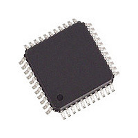
82V2081PPG8 IDT, Integrated Device Technology Inc, 82V2081PPG8 Datasheet - Page 29

82V2081PPG8
Manufacturer Part Number
82V2081PPG8
Description
Manufacturer
IDT, Integrated Device Technology Inc
Datasheet
1.82V2081PPG8.pdf
(68 pages)
Specifications of 82V2081PPG8
Number Of Transceivers
1
Screening Level
Industrial
Mounting
Surface Mount
Package Type
TQFP
Operating Temperature (min)
-40C
Operating Temperature (max)
85C
Lead Free Status / RoHS Status
Compliant
SINGLE CHANNEL T1/E1/J1 LONG HAUL/SHORT HAUL LINE INTERFACE UNIT
3.9
3.9.1
IDT82V2081:
•
Table-21 EXZ Definition
3.9.2
zero errors and PRBS logic errors) will be counted is determined by
ERR_SEL[1:0] bits (MAINT6, 13H). Only one type of receiving error can be
counted at a time except that when the ERR_SEL[1:0] bits are set to ‘11’,
both CV/BPV and EXZ errors will be detected and counted.
Counter. Once an error is detected, an error interrupt which is indicated by
corresponding bit in (INTS1, 1AH) will be generated if it is not masked. This
Error Counter can be operated in two modes: Auto Report Mode and Man-
ual Report Mode, as selected by the CNT_MD bit (MAINT6, 13H). In Single
Rail mode, once BPV or CV errors are detected, the CV pin will be driven
to high for one RCLK period.
errors when the CNT_MD bit (MAINT6, 13H) is set to ‘1’. A one-second timer
is used to set the counting period. The received errors are counted within
one second. If the one-second timer expires, the value in the internal
counter will be transferred to (CNT0, 1BH) and (CNT1, 1CH), then the inter-
nal counter will be reset and start to count received errors for the next sec-
ond. The errors occurred during the transfer will be accumulated to the next
round. The expiration of the one-second timer will set TMOV_IS bit (INTS1,
1AH) to ‘1’, and will generate an interrupt if the TIMER_IM bit (INTM1, 15H)
is set to ‘0’. The TMOV_IS bit (INTS1, 1AH) will be cleared after the interrupt
register is read. The content in the (CNT0, 1BH) and (CNT1, 1CH) should
be read within the next second. If the counter overflows, a counter overflow
interrupt which is indicated by CNT_OV_IS bit (INTS1, 1AH) will be gener-
ated if it is not masked by CNT_IM bit (INTM1, 15H).
The following line encoding errors can be detected and counted by the
Which type of the receiving errors (Received CV/BPV errors, excess
The selected type of receiving errors is counted in an internal 16-bit Error
• Auto Report Mode
In Auto Report Mode, the internal counter starts to count the received
Received Bipolar Violation (BPV) Error: In AMI coding, when two
consecutive pulses of the same polarity are received, a BPV error
is declared.
HDB3
B8ZS
AMI
ERROR DETECTION/COUNTING AND INSERTION
DEFINITION OF LINE CODING ERROR
ERROR DETECTION AND COUNTING
More than 15 consecutive 0s are detected
More than 3 consecutive 0s are detected
More than 7 consecutive 0s are detected
ANSI
29
•
•
EXZ Definition
HDB3/B8ZS Code Violation (CV) Error: In HDB3/B8ZS coding, a
CV error is declared when two consecutive BPV errors are
detected, and the pulses that have the same polarity as the previ-
ous pulse are not the HDB3/B8ZS zero substitution pulses.
Excess Zero (EXZ) Error: There are two standards defining the
EXZ errors: ANSI and FCC. The EXZ_DEF bit (MAINT6, 13H)
chooses which standard will be adopted by the chip to judge the
EXZ error.
mode, only ANSI standard is adopted.
N
Table-21
Figure-16 Auto Report Mode
read the data in CNT0, CNT1 within
the next second
CNT0, CNT1
counter
More than 80 consecutive 0s are detected
More than 3 consecutive 0s are detected
More than 7 consecutive 0s are detected
One-Second Timer expired?
Bit TMOV_IS is cleared after
the interrupt register is read
Bit TMOV_IS is set to '1'
shows definition of EXZ. In hardware
Auto Report Mode
(CNT_MD=1)
counting
0
data in counter
Y
FCC
TEMPERATURE RANGES
same process
next second
INDUSTRIAL
repeats the
control


