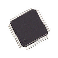
82V2081PPG8 IDT, Integrated Device Technology Inc, 82V2081PPG8 Datasheet - Page 37

82V2081PPG8
Manufacturer Part Number
82V2081PPG8
Description
Manufacturer
IDT, Integrated Device Technology Inc
Datasheet
1.82V2081PPG8.pdf
(68 pages)
Specifications of 82V2081PPG8
Number Of Transceivers
1
Screening Level
Industrial
Mounting
Surface Mount
Package Type
TQFP
Operating Temperature (min)
-40C
Operating Temperature (max)
85C
Lead Free Status / RoHS Status
Compliant
SINGLE CHANNEL T1/E1/J1 LONG HAUL/SHORT HAUL LINE INTERFACE UNIT
Table-30 TCF1: Transmitter Configuration Register 1
Table-31 TCF2: Transmitter Configuration Register 2
1. In internal impedance matching mode, for E1/75 Ω cable impedance, the PULS[3:0] bits ( TCF1, 06H ) should be set to ‘0000’. In external impedance matching mode, for E1/75 Ω cable
DFM_OFF
PULS[3:0]
impedance, the PULS[3:0] bits should be set to ‘0001’.
SCAL[5:0]
Symbol
Symbol
THZ
-
-
(R/W, Address = 06H)
(R/W, Address = 07H)
Bit
7-6
3-0
5
4
7-6
5-0
Bit
Default
0000
00
1
0
Default
100001
00
Reserved. This bit should be ‘0’ for normal operation.
Transmit driver failure monitor disable
= 0: DFM is enabled
= 1: DFM is disabled
Transmit line driver high impedance enable
= 0: Normal state
= 1: Transmit line driver high impedance enable (other transmit path still work normally)
These bits select the transmit template/LBO for short-haul/long-haul applications.
0000
0001
0010
0100
0101
1000
1001
1010
11XX
0011
0110
0111
1011
Reserved.
SCAL specifies a scaling factor to be applied to the amplitude of the user-programmable arbitrary pulses which is
to be transmitted if needed. The default value of SCAL[5:0] is ‘100001’. Refer to
trary
= 110110: Default value for T1 0~133 ft, T1 133~266 ft, T1 266~399 ft, T1 399~533 ft, T1 533~655 ft, J1 0~655 ft,
= 010001: Default value for DS1 -7.5 dB LBO. One step change of this value results in 6.25% scaling up/down
= 001000: Default value for DS1 -15.0 dB LBO. One step change of this value results in 12.5% scaling up/down
= 000100: Default value for DS1 -22.5 dB LBO. One step change of this value results in 25% scaling up/down
= 100001: Default value for E1 75 Ω and 120 Ω. One step change of this value results in 3% scaling up/down
DS1 0dB LBO. One step change of this value results in 2% scaling up/down against the pulse amplitude.
against the pulse amplitude.
against the pulse amplitude.
against the pulse amplitude.
against the pulse amplitude.
1
Waveform.
T1/E1/J1
DSX1
DSX1
DSX1
DSX1
DSX1
DS1
DS1
DS1
DS1
E1
E1
J1
37
2.048 MHz
2.048 MHz
1.544 MHz
1.544 MHz
1.544 MHz
1.544 MHz
1.544 MHz
1.544 MHz
1.544 MHz
1.544 MHz
1.544 MHz
1.544 MHz
TCLK
User programmable waveform setting
Description
Description
Cable impedance
120 Ω
100 Ω
100 Ω
100 Ω
100 Ω
100 Ω
110 Ω
100 Ω
100 Ω
100 Ω
100 Ω
75 Ω
Cable range or
-15.0 dB LBO
-22.5 dB LBO
-7.5 dB LBO
133-266 ft
266-399 ft
399-533 ft
533-655 ft
0 dB LBO
0-133 ft
0-655 ft
3.3.3.3 User-Programmable Arbi-
TEMPERATURE RANGES
LBO
-
-
Allowable Cable
INDUSTRIAL
0.6-1.2 dB
1.2-1.8 dB
1.8-2.4 dB
2.4-3.0 dB
0-28.5 dB
0-13.5 dB
0-0.6 dB
0-3.0 dB
0-43 dB
0-43 dB
0-36 dB
0-21 dB
loss


