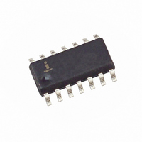
X1228S14IZ Intersil, X1228S14IZ Datasheet - Page 26

X1228S14IZ
Manufacturer Part Number
X1228S14IZ
Description
IC RTC/CAL/SUP/ALRM 4K EE 14SOIC
Manufacturer
Intersil
Type
Clock/Calendar/EEPROMr
Datasheet
1.X1228S14-2.7A.pdf
(29 pages)
Specifications of X1228S14IZ
Memory Size
4K (512 x 8)
Time Format
HH:MM:SS (12/24 hr)
Date Format
YY-MM-DD-dd
Interface
I²C, 2-Wire Serial
Voltage - Supply
2.7 V ~ 5.5 V
Operating Temperature
-40°C ~ 85°C
Mounting Type
Surface Mount
Package / Case
14-SOIC (3.9mm Width), 14-SOL
Lead Free Status / RoHS Status
Lead free / RoHS Compliant
Available stocks
Company
Part Number
Manufacturer
Quantity
Price
Company:
Part Number:
X1228S14IZ
Manufacturer:
NXP
Quantity:
906
Part Number:
X1228S14IZ-2.7A
Manufacturer:
INTERSIL
Quantity:
20 000
Backup Battery Operation
Many types of batteries can be used with the Intersil
RTC products. 3.0V or 3.6V Lithium batteries are
appropriate, and sizes are available that can power a
Intersil RTC device for up to 10 years. Another option
is to use a supercapacitor for applications where Vcc
may disappear intermittently for short periods of time.
Depending on the value of supercapacitor used,
backup time can last from a few days to two weeks
(with >1F). A simple silicon or Schottky barrier diode
can be used in series with Vcc to charge the superca-
pacitor, which is connected to the Vback pin. Do not
use the diode to charge a battery (especially lithium
batteries!).
Table 8. Battery Backup Operation
*since Vback>2.65V is higher than Vtrip, the battery is powering the entire device
1. Example Application, Vcc = 5V, Vback = 3.0V
a. Normal Operation
b. Vcc on with no battery
c. Backup Mode
2. Example Application, Vcc = 3.3V,Vback = 3.0V
a. Normal Operation
b. Vcc on with no battery
c. Backup Mode
d. UNWANTED - Vcc ON, Vback
powering
Condition
Condition
26
2.65 - 3.30
0-1.8
0-1.8
5.00
5.00
3.30
3.30
Vcc
Vcc
1.8-3.0*
Vback
1.8-3.0
Vback
> Vcc
X1228
3.00
3.00
0
0
Figure 16. Supercapactor charging circuit
Since the battery switchover occurs at Vcc=Vback-
0.1V (see Figure 16), the battery voltage must always
be lower than the Vcc voltage during normal operation
or the battery will be drained. A second consideration
is the trip point setting for the system RESET- func-
tion, known as Vtrip. Vtrip is set at the factory at levels
for systems with either Vcc = 5V or 3.3V operation,
with the following standard options:
V
V
V
V
The summary of conditions for backup battery opera-
tion is given in Table 8:
TRIP
TRIP
TRIP
TRIP
2.7-5.5V
Vtrip
Vtrip
4.38
4.38
4.38
2.65
2.65
2.65
2.65
= 4.63V ± 3%
= 4.38V ± 3%
= 2.85V ± 3%
= 2.65V ± 3%
up to 3mA
<<1µA
<<1µA
V
Iback
Iback
<2µA*
<2µA
CC
0
0
V
SS
V
back
Reset
Reset
H
H
H
H
H
L
L
Timekeeping
Timekeeping
Vcc=Vback
Supercapacitor
Internal
Notes
only
only
May 18, 2006
FN8100.4


