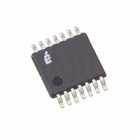
X1288V14T1 Intersil, X1288V14T1 Datasheet - Page 23

X1288V14T1
Manufacturer Part Number
X1288V14T1
Description
IC RTC/CAL/CPU SUP EE 14-TSSOP
Manufacturer
Intersil
Type
Clock/Calendar/Supervisor/EEPROMr
Datasheet
1.X1288S16.pdf
(27 pages)
Specifications of X1288V14T1
Memory Size
256K (32K x 8)
Time Format
HH:MM:SS:hh (12/24 hr)
Date Format
YY-MM-DD-dd
Interface
I²C, 2-Wire Serial
Voltage - Supply
4.5 V ~ 5.5 V
Operating Temperature
-40°C ~ 85°C
Mounting Type
Surface Mount
Package / Case
14-TSSOP
Lead Free Status / RoHS Status
Contains lead / RoHS non-compliant
Table 7. Crystal Parameters Required for Intersil RTC’s
Table 8. Crystal Manufacturers
A final application for the ATR control is in-circuit cali-
bration for high accuracy applications, along with a
temperature sensor chip. Once the RTC circuit is pow-
ered up with battery backup, the PHZ output is set at
32.768kHz and frequency drift is measured. The ATR
control is then adjusted to a setting which minimizes
drift. Once adjusted at a particular temperature, it is
possible to adjust at other discrete temperatures for
minimal overall drift, and store the resulting settings in
the EEPROM. Extremely low overall temperature drift
is possible with this method. The Intersil evaluation
board contains the circuitry necessary to implement
this control.
For more detailed operation see Intersil’s application
note AN154 on Intersil’s website at www.intersil.com.
Layout Considerations
The crystal input at X1 has a very high impedance and
will pick up high frequency signals from other circuits
on the board. Since the X2 pin is tied to the other side
of the crystal, it is also a sensitive node. These signals
can couple into the oscillator circuit and produce dou-
ble clocking or mis-clocking, seriously affecting the
accuracy of the RTC. Care needs to be taken in layout
of the RTC circuit to avoid noise pickup. Below in Fig-
ure 19 is a suggested layout for the X1286 or X1288
devices.
Frequency
Freq. Tolerance
Turnover Temperature
Operating Temperature Range
Parallel Load Capacitance
Equivalent Series Resistance
Citizen
Epson
Raltron
SaRonix
Ecliptek
ECS
Fox
Manufacturer
Parameter
CM201, CM202, CM200S
MC-405, MC-406
RSM-200S-A or B
32S12A or B
ECPSM29T-32.768K
ECX-306/ECX-306I
FSM-327
23
Part Number
Min
-40
20
32.768
12.5
Typ
25
X1288
±100
Max
30
85
50
Temp Range
The X1 and X2 connections to the crystal are to be
kept as short as possible. A thick ground trace around
the crystal is advised to minimize noise intrusion, but
ground near the X1 and X2 pins should be avoided as
it will add to the load capacitance at those pins. Keep
in mind these guidelines for other PCB layers in the
vicinity of the RTC device. A small decoupling capaci-
tor at the Vcc pin of the chip is mandatory, with a solid
connection to ground.
The X1286 product has a special consideration. The
PHZ/IRQ- pin on the 8-lead SOIC package is located
next to the X2 pin. When this pin is used as a fre-
quency output (PHZ) and is set to 32.768kHz output
frequency, noise can couple to the X1 or X2 pins and
cause double-clocking. The layout in Figure 19 can
help minimize this by running the PHZ output away
-40 to +85°C
-40 to +85°C
-40 to +85°C
-40 to +85°C
-10 to +60°C
-10 to +60°C
-40 to +85°C
FIGURE 19. SUGGESTED LAYOUT FOR INTERSIL RTC IN SO-8
32.768kGz
XTAL1
Units
ppm
kHz
kΩ
°C
°C
pF
Down to 20ppm if desired
Typically the value used for most
crystals
For best oscillator performance
X1286/X1288
+25°C Freq Toler.
U1
R1 10k
Notes
±20ppm
±20ppm
±20ppm
±20ppm
±20ppm
±20ppm
±20ppm
April 14, 2006
FN8102.3
C1
0.1µF


