ADC0804LCN Intersil, ADC0804LCN Datasheet - Page 10
ADC0804LCN
Manufacturer Part Number
ADC0804LCN
Description
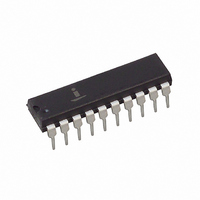
IC ADC 8-BIT 10KSPS 1LSB 20-DIP
Manufacturer
Intersil
Datasheet
1.ADC0804LCN.pdf
(17 pages)
Specifications of ADC0804LCN
Number Of Bits
8
Sampling Rate (per Second)
10k
Data Interface
Parallel
Number Of Converters
1
Voltage Supply Source
Single Supply
Operating Temperature
0°C ~ 70°C
Mounting Type
Through Hole
Package / Case
20-DIP (0.300", 7.62mm)
Lead Free Status / RoHS Status
Contains lead / RoHS non-compliant
Other names
ADC0804LCNIN
ADC0804LCNIN
ADC0804LCNIN
Available stocks
Company
Part Number
Manufacturer
Quantity
Price
Company:

Part Number:
ADC0804LCN
Manufacturer:
MICROCHIP
Quantity:
2 000
Company:
Part Number:
ADC0804LCN
Manufacturer:
NS
Quantity:
432
Company:
Part Number:
ADC0804LCN
Manufacturer:
TI
Quantity:
100
Part Number:
ADC0804LCN
Manufacturer:
NS/国半
Quantity:
20 000
Company:
Part Number:
ADC0804LCN*
Manufacturer:
S/PHI
Quantity:
19
Company:
Part Number:
ADC0804LCN/NOPB
Manufacturer:
MICRON
Quantity:
1 000


Such an adjusted reference voltage can accommodate a
reduced span or dynamic voltage range of the analog input
voltage. If the analog input voltage were to range from 0.5V to
3.5V, instead of 0V to 5V, the span would be 3V. With 0.5V
applied to the V
voltage can be made equal to
A/D now will encode the V
the 0.5V input corresponding to zero and the 3.5V input
corresponding to full scale. The full 8 bits of resolution are
therefore applied over this reduced analog input voltage
range. The requisite connections are shown in Figure 13. For
expanded scale inputs, the circuits of Figures 14 and 15 can
be used.
V
V
FIGURE 13. OFFSETTING THE ZERO OF THE ADC080X AND
REF
REF
ADJ.
/2
(5V)
FS
FIGURE 12. THE V
9
“SPAN”/2
PERFORMING AN INPUT RANGE (SPAN)
ADJUSTMENT
AGND
lN(-)
ICL7611
R
R
ZERO SHIFT VOLTAGE
pin to absorb the offset, the reference
+
-
8
DECODE
REFERENCE
5V
lN(+)
10
1
/
signal from 0.5V to 3.5V with
2
of the 3V span or 1.5V. The
300
0.1 F
DESIGN ON THE IC
(V
V+
REF
CIRCUITS
ANALOG
)
DGND
20
CIRCUITS
DIGITAL
TO V
TO V
ADC0803, ADC0804
10
REF
IN(-)
/2
Reference Accuracy Requirements
The converter can be operated in a pseudo-ratiometric mode
or an absolute mode. In ratiometric converter applications,
the magnitude of the reference voltage is a factor in both the
output of the source transducer and the output of the A/D
converter and therefore cancels out in the final digital output
code. In absolute conversion applicatIons, both the initial
value and the temperature stability of the reference voltage
are important accuracy factors in the operation of the A/D
converter. For V
errors of 10mV will cause conversion errors of 1 LSB due
to the gain of 2 of the V
applications, the initial value and the stability of the V
input voltage become even more important. For example, if
the span is reduced to 2.5V, the analog input LSB voltage
value is correspondingly reduced from 20mV (5V span) to
10mV and 1 LSB at the V
be seen, this reduces the allowed initial tolerance of the
reference voltage and requires correspondingly less
absolute change with temperature variations. Note that
spans smaller than 2.5V place even tighter requirements on
the initial accuracy and stability of the reference source.
In general, the reference voltage will require an initial
adjustment. Errors due to an improper value of reference
voltage appear as full scale errors in the A/D transfer
V
V
IN
IN
FIGURE 14. HANDLING 10V ANALOG INPUT RANGE
FIGURE 15. HANDLING 5V ANALOG INPUT RANGE
10V
5V
2R
R
REF
/2 voltages of 2.5V nominal value, initial
R
2R
R
REF
REF
6
7
6
7
/2 input. In reduced span
V
V
V
V
ADC0803-
ADC0803-
ADC0804
ADC0804
/2 input becomes 5mV. As can
IN(+)
IN(-)
IN(+)
IN(-)
V+
V+
20
20
+
+
10 F
10 F
REF
(V
(V
5V
5V
REF
REF
/2
)
)
Related parts for ADC0804LCN
Image
Part Number
Description
Manufacturer
Datasheet
Request
R

Part Number:
Description:
Intersil Corporation [CMOS Serial Controller Interface]
Manufacturer:
Intersil Corporation
Datasheet:
Part Number:
Description:
Manufacturer:
Intersil Corporation
Datasheet:
Part Number:
Description:
357-036-542-201 CARDEDGE 36POS DL .156 BLK LOPRO
Manufacturer:
Intersil Corporation
Datasheet:
Part Number:
Description:
1024-Word x 4-Bit LSI Static RAM
Manufacturer:
Intersil Corporation
Datasheet:
Part Number:
Description:
General Purpose NPN Transistor Arrays FN341.4
Manufacturer:
Intersil Corporation
Datasheet:
Part Number:
Description:
CMOS 16-Bit Microprocessor
Manufacturer:
Intersil Corporation
Datasheet:
Part Number:
Description:
Manufacturer:
Intersil Corporation
Datasheet:
Part Number:
Description:
Manufacturer:
Intersil Corporation
Datasheet:
Part Number:
Description:
Manufacturer:
Intersil Corporation
Datasheet:
Part Number:
Description:
Manufacturer:
Intersil Corporation
Datasheet:
Part Number:
Description:
CMOS 6-Bit Latch and Decoder Memory Interfaces
Manufacturer:
Intersil Corporation
Datasheet:
Part Number:
Description:
CA3046General Purpose NPN Transistor Arrays
Manufacturer:
Intersil Corporation
Datasheet:
Part Number:
Description:
Manufacturer:
Intersil Corporation
Datasheet:
Part Number:
Description:
TR909 DLC/FLC SLIC with Low Power Standby
Manufacturer:
Intersil Corporation
Datasheet:
Part Number:
Description:
Manufacturer:
Intersil Corporation
Datasheet: