ADC0804LCN Intersil, ADC0804LCN Datasheet - Page 13
ADC0804LCN
Manufacturer Part Number
ADC0804LCN
Description
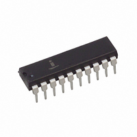
IC ADC 8-BIT 10KSPS 1LSB 20-DIP
Manufacturer
Intersil
Datasheet
1.ADC0804LCN.pdf
(17 pages)
Specifications of ADC0804LCN
Number Of Bits
8
Sampling Rate (per Second)
10k
Data Interface
Parallel
Number Of Converters
1
Voltage Supply Source
Single Supply
Operating Temperature
0°C ~ 70°C
Mounting Type
Through Hole
Package / Case
20-DIP (0.300", 7.62mm)
Lead Free Status / RoHS Status
Contains lead / RoHS non-compliant
Other names
ADC0804LCNIN
ADC0804LCNIN
ADC0804LCNIN
Available stocks
Company
Part Number
Manufacturer
Quantity
Price
Company:

Part Number:
ADC0804LCN
Manufacturer:
MICROCHIP
Quantity:
2 000
Company:
Part Number:
ADC0804LCN
Manufacturer:
NS
Quantity:
432
Company:
Part Number:
ADC0804LCN
Manufacturer:
TI
Quantity:
100
Part Number:
ADC0804LCN
Manufacturer:
NS/国半
Quantity:
20 000
Company:
Part Number:
ADC0804LCN*
Manufacturer:
S/PHI
Quantity:
19
Company:
Part Number:
ADC0804LCN/NOPB
Manufacturer:
MICRON
Quantity:
1 000


This converter has been designed to directly interface with
8080/85 or Z-80 Microprocessors. The three-state output
capability of the A/D eliminates the need for a peripheral
interface device, although address decoding is still required
to generate the appropriate CS for the converter. The A/D
can be mapped into memory space (using standard
memory-address decoding for CS and the MEMR and
MEMW strobes) or it can be controlled as an I/O device by
using the I/OR and I/OW strobes and decoding the address
bits A0
contain the same 8-bit address information) to obtain the CS
input. Using the I/O space provides 256 additional
addresses and may allow a simpler 8-bit address decoder,
but the data can only be input to the accumulator. To make
use of the additional memory reference instructions, the A/D
should be mapped into memory space. See AN020 for more
discussion of memory-mapped vs I/O-mapped interfaces. An
example of an A/D in I/O space is shown in Figure 21.
The standard control-bus signals of the 8080 (CS, RD and
WR) can be directly wired to the digital control inputs of the
A/D, since the bus timing requirements, to allow both starting
the converter, and outputting the data onto the data bus, are
met. A bus driver should be used for larger microprocessor
systems where the data bus leaves the PC board and/or
must drive capacitive loads larger than 100pF.
It is useful to note that in systems where the A/D converter is
1 of 8 or fewer I/O-mapped devices, no address-decoding
circuitry is necessary. Each of the 8 address bits (A0 to A7)
can be directly used as CS inputs, one for each I/O device.
Interfacing the Z-80 and 8085
The Z-80 and 8085 control buses are slightly different from
that of the 8080. General RD and WR strobes are provided
and separate memory request, MREQ, and I/O request,
IORQ, signals have to be combined with the generalized
strobes to provide the appropriate signals. An advantage of
operating the A/D in I/O space with the Z-80 is that the CPU
will automatically insert one wait state (the RD and WR
strobes are extended one clock period) to allow more time
for the I/O devices to respond. Logic to map the A/D in I/O
space is shown in Figure 22. By using MREQ in place of
IORQ, a memory-mapped configuration results.
Additional I/O advantages exist as software DMA routines are
available and use can be made of the output data transfer
which exists on the upper 8 address lines (A8 to A15) during
I/O input instructions. For example, MUX channel selection for
the A/D can be accomplished with this operating mode.
The 8085 also provides a generalized RD and WR strobe, with
an IO/M line to distinguish I/O and memory requests. The circuit
of Figure 22 can again be used, with IO/M in place of IORQ for
a memory-mapped interface, and an extra inverter (or the logic
equivalent) to provide IO/M for an I/O-mapped connection.
A7 (or address bits A8
13
A15, since they will
ADC0803, ADC0804
Interfacing 6800 Microprocessor Derivatives (6502,
etc.)
The control bus for the 6800 microprocessor derivatives does
not use the RD and WR strobe signals. Instead it employs a
single R/W line and additional timing, if needed, can be derived
from the 2 clock. All I/O devices are memory-mapped in the
6800 system, and a special signal, VMA, indicates that the
current address is valid. Figure 23 shows an interface
schematic where the A/D is memory-mapped in the 6800
system. For simplicity, the CS decoding is shown using
DM8092. Note that in many 6800 systems, an already decoded
4/5 line is brought out to the common bus at pin 21. This can be
tied directly to the CS pin of the A/D, provided that no other
devices are addressed at HEX ADDR: 4XXX or 5XXX.
In Figure 24 the ADC080X series is interfaced to the MC6800
microprocessor through (the arbitrarily chosen) Port B of the
MC6820 or MC6821 Peripheral Interface Adapter (PlA). Here
the CS pin of the A/D is grounded since the PlA is already
memory-mapped in the MC6800 system and no CS decoding
is necessary. Also notice that the A/D output data lines are
connected to the microprocessor bus under program control
through the PlA and therefore the A/D RD pin can be grounded.
Application Notes
AN016
AN018
AN020
AN030
NOTE #
“Selecting A/D Converters”
“Do’s and Don’ts of Applying A/D Converters”
“A Cookbook Approach to High Speed Data Acquisition
and Microprocessor Interfacing”
“The ICL7104 - A Binary Output A/D Converter for
Microprocessors”
DESCRIPTION
1
/
2
Related parts for ADC0804LCN
Image
Part Number
Description
Manufacturer
Datasheet
Request
R

Part Number:
Description:
Intersil Corporation [CMOS Serial Controller Interface]
Manufacturer:
Intersil Corporation
Datasheet:
Part Number:
Description:
Manufacturer:
Intersil Corporation
Datasheet:
Part Number:
Description:
357-036-542-201 CARDEDGE 36POS DL .156 BLK LOPRO
Manufacturer:
Intersil Corporation
Datasheet:
Part Number:
Description:
1024-Word x 4-Bit LSI Static RAM
Manufacturer:
Intersil Corporation
Datasheet:
Part Number:
Description:
General Purpose NPN Transistor Arrays FN341.4
Manufacturer:
Intersil Corporation
Datasheet:
Part Number:
Description:
CMOS 16-Bit Microprocessor
Manufacturer:
Intersil Corporation
Datasheet:
Part Number:
Description:
Manufacturer:
Intersil Corporation
Datasheet:
Part Number:
Description:
Manufacturer:
Intersil Corporation
Datasheet:
Part Number:
Description:
Manufacturer:
Intersil Corporation
Datasheet:
Part Number:
Description:
Manufacturer:
Intersil Corporation
Datasheet:
Part Number:
Description:
CMOS 6-Bit Latch and Decoder Memory Interfaces
Manufacturer:
Intersil Corporation
Datasheet:
Part Number:
Description:
CA3046General Purpose NPN Transistor Arrays
Manufacturer:
Intersil Corporation
Datasheet:
Part Number:
Description:
Manufacturer:
Intersil Corporation
Datasheet:
Part Number:
Description:
TR909 DLC/FLC SLIC with Low Power Standby
Manufacturer:
Intersil Corporation
Datasheet:
Part Number:
Description:
Manufacturer:
Intersil Corporation
Datasheet: