MC68EC020AA25 Freescale Semiconductor, MC68EC020AA25 Datasheet - Page 42
MC68EC020AA25
Manufacturer Part Number
MC68EC020AA25
Description
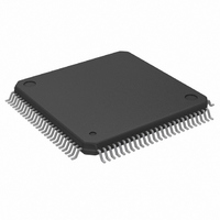
IC MPU 32BIT 25MHZ 100-QFP
Manufacturer
Freescale Semiconductor
Datasheet
1.MC68EC020AA16.pdf
(306 pages)
Specifications of MC68EC020AA25
Processor Type
M680x0 32-Bit
Speed
25MHz
Voltage
5V
Mounting Type
Surface Mount
Package / Case
100-QFP
Family Name
M68000
Device Core
ColdFire
Device Core Size
32b
Frequency (max)
25MHz
Instruction Set Architecture
RISC
Supply Voltage 1 (typ)
5V
Operating Supply Voltage (max)
5.25V
Operating Supply Voltage (min)
4.75V
Operating Temp Range
0C to 70C
Operating Temperature Classification
Commercial
Mounting
Surface Mount
Pin Count
100
Package Type
PQFP
Lead Free Status / RoHS Status
Lead free / RoHS Compliant
Features
-
Lead Free Status / Rohs Status
RoHS Compliant part
Electrostatic Device
Available stocks
Company
Part Number
Manufacturer
Quantity
Price
Company:

Part Number:
MC68EC020AA25
Manufacturer:
Freescale Semiconductor
Quantity:
10 000
Company:
Part Number:
MC68EC020AA25R
Manufacturer:
Freescale Semiconductor
Quantity:
10 000


Halt (HALT)
Bus Error (BERR)
3.10 EMULATOR SUPPORT SIGNAL
The following signal supports emulation by providing a means for an emulator to disable
the on-chip cache by supplying internal status information to an emulator. Refer to
Section 7 Coprocessor Interface Description for more detailed information on
emulation support.
Cache Disable (CDIS)
3.11 CLOCK (CLK)
The CLK signal is the clock input to the MC68020/EC020. This TTL-compatible signal
should not be gated off at any time while power is applied to the processor. Refer to
Section 9 Applications Information for suggestions on clock generation. Refer to
Section 10 Electrical Characteristics for electrical characteristics.
3.12 POWER SUPPLY CONNECTIONS
The MC68020/EC020 requires connection to a V
ground. The V
sections of the processor. The ground connections are similarly grouped. Section 11
Ordering Information and Mechanical Data describes the groupings of V
connections, and Section 9 Applications Information describes a typical power supply
interface.
MOTOROLA
The assertion of this bidirectional open-drain signal indicates that the processor should
suspend bus activity or, when used with BERR , that the processor should retry the
current cycle. Refer to Section 5 Bus Operation for a description of the effects of
HALT on bus operations. When the processor has stopped executing instructions due
to a double bus fault condition, the HALT line is asserted by the processor to indicate to
external devices that the processor has stopped.
This input signal indicates that an invalid bus operation is being attempted or, when
used with HALT , that the processor should retry the current cycle. Refer to Section 5
Bus Operation for a description of the effects of BERR on bus operations.
This input signal statically disables the on-chip cache to assist emulator support. Refer
to Section 4 On-Chip Cache Memory for information about the cache; refer to Section
9 Applications Information for a description of the use of this signal by an emulator.
CDIS does not flush the instruction cache; entries remain unaltered and become
available again when CDIS is negated.
CC
connections are grouped to supply adequate current for the various
M68020 USER’S MANUAL
CC
power supply, positive with respect to
CC
and ground
3- 7
Related parts for MC68EC020AA25
Image
Part Number
Description
Manufacturer
Datasheet
Request
R

Part Number:
Description:
Manufacturer:
Freescale Semiconductor, Inc
Datasheet:
Part Number:
Description:
Manufacturer:
Freescale Semiconductor, Inc
Datasheet:
Part Number:
Description:
Manufacturer:
Freescale Semiconductor, Inc
Datasheet:
Part Number:
Description:
Manufacturer:
Freescale Semiconductor, Inc
Datasheet:
Part Number:
Description:
Manufacturer:
Freescale Semiconductor, Inc
Datasheet:
Part Number:
Description:
Manufacturer:
Freescale Semiconductor, Inc
Datasheet:
Part Number:
Description:
Manufacturer:
Freescale Semiconductor, Inc
Datasheet:
Part Number:
Description:
Manufacturer:
Freescale Semiconductor, Inc
Datasheet:
Part Number:
Description:
Manufacturer:
Freescale Semiconductor, Inc
Datasheet:
Part Number:
Description:
Manufacturer:
Freescale Semiconductor, Inc
Datasheet:
Part Number:
Description:
Manufacturer:
Freescale Semiconductor, Inc
Datasheet:
Part Number:
Description:
Manufacturer:
Freescale Semiconductor, Inc
Datasheet:
Part Number:
Description:
Manufacturer:
Freescale Semiconductor, Inc
Datasheet:
Part Number:
Description:
Manufacturer:
Freescale Semiconductor, Inc
Datasheet:
Part Number:
Description:
Manufacturer:
Freescale Semiconductor, Inc
Datasheet: