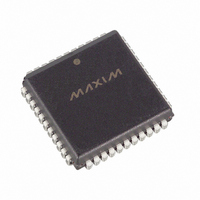
DS2141AQ+ Maxim Integrated Products, DS2141AQ+ Datasheet - Page 10

DS2141AQ+
Manufacturer Part Number
DS2141AQ+
Description
IC CONTROLLER T1 5V 44-PLCC
Manufacturer
Maxim Integrated Products
Datasheet
1.DS2141AQ.pdf
(39 pages)
Specifications of DS2141AQ+
Controller Type
T1 Controller
Interface
Parallel/Serial
Voltage - Supply
4.5 V ~ 5.5 V
Current - Supply
10mA
Operating Temperature
0°C ~ 70°C
Mounting Type
Surface Mount
Package / Case
44-LCC, 44-PLCC
Operating Supply Voltage
5 V
Supply Current (max)
10 mA
Maximum Operating Temperature
+ 70 C
Minimum Operating Temperature
0 C
Mounting Style
SMD/SMT
Lead Free Status / RoHS Status
Lead free / RoHS Compliant
TCR2: TRANSMIT CONTROL REGISTER 2 (36h)
(MSB)
TESTM
SYMBOL
TESTIO
TD4YM
TZBTSI
TESTM
TSDW
B7ZS
TSIO
TSM
TESTIO
POSITION
TCR2.7
TCR2.6
TCR2.5
TCR2.4
TCR2.3
TCR2.2
TCR2.1
TCR2.0
TZBTSI
NAME AND DESCRIPTION
Test Mode Select. Set this bit to a 1 to force all outputs
(including I/O pins) either high (TCR2.6 = 1) or low (TCR2.6 =
0).
Test I/O Pins.
0=force all output (and I/O) pins to a logic 0.
1=force all output (and I/O) pins to a logic 1.
Transmit Side ZBTSI Enable.
0=ZBTSI disabled.
1=ZBTSI enabled.
TSYNC Double-Wide.
0=do not pulse double-wide in signaling frames.
1=do pulse double-wide in signaling frames.
(note: this bit must be set to 0 when TCR 2.3 = 1 or when
TCR2.2 = 0).
TSYNC Mode Select.
0=frame mode (see the timing in Section 13).
1=multiframe mode (see the timing in Section 13).
TSYNC I/O Select.
0=TSYNC is an input.
1=TSYNC is an output.
Transmit Side D4 Yellow Alarm Select.
0=0s in bit 2 of all channels.
1=a 1 in the S-bit position of frame 12.
Bit 7 Zero Suppression Enable.
0=no stuffing occurs.
1=Bit 7 forced to a 1 in channels with all 0s.
TSDW
10 of 39
TSM
TSIO
TD4YM
(LSB)
B7ZS
DS2141A


