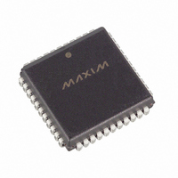
DS2141AQ+ Maxim Integrated Products, DS2141AQ+ Datasheet - Page 6

DS2141AQ+
Manufacturer Part Number
DS2141AQ+
Description
IC CONTROLLER T1 5V 44-PLCC
Manufacturer
Maxim Integrated Products
Datasheet
1.DS2141AQ.pdf
(39 pages)
Specifications of DS2141AQ+
Controller Type
T1 Controller
Interface
Parallel/Serial
Voltage - Supply
4.5 V ~ 5.5 V
Current - Supply
10mA
Operating Temperature
0°C ~ 70°C
Mounting Type
Surface Mount
Package / Case
44-LCC, 44-PLCC
Operating Supply Voltage
5 V
Supply Current (max)
10 mA
Maximum Operating Temperature
+ 70 C
Minimum Operating Temperature
0 C
Mounting Style
SMD/SMT
Lead Free Status / RoHS Status
Lead free / RoHS Compliant
2.0 PARALLEL PORT
The DS2141A is controlled via a multiplexed bidirectional address/data bus by an external
microcontroller or microprocessor. The DS2141A can operate with either Intel or Motorola bus timing
configurations. If the BTS pin is tied low, Intel timing will be selected; if tied high, Motorola timing will
be selected. All Motorola bus signals are listed in parentheses (). See the timing diagrams in the AC
Electrical Characteristics for more details. The multiplexed bus on the DS2141A saves pins because the
address information and data information share the same signal paths. The addresses are presented to the
pins in the first portion of the bus cycle and data will be transferred on the pins during second portion of
the bus cycle. Addresses must be valid prior to the falling edge of ALE(AS), at which time the DS2141A
latches the address from the AD0 to AD7 pins. Valid write data must be present and held stable during
the later portion of the DS or
latter portion of the DS or
impedance state as
3.0 CONTROL REGISTERS
The operation of the DS2141A is configured via a set of six registers. Typically, the control registers are
only accessed when the system is first powered up. Once, the DS2141A has been initialized, the control
registers will only need to be accessed when there is a change in the system configuration. There are two
Receive Control Registers (RCR1 and RCR2), two Transmit Control Registers (TCR1 and TCR2), and
two Common Control Registers (CCR1 and CCR2). Each of the six registers is described below.
ADDRESS R/W
6A
6B
6C
6D
6E
6F
65
66
67
68
69
70
71
72
R/W Receive Channel
R/W Receive Channel
R/W Receive Channel
R/W Interrupt Mask Register 2
R/W Transmit Signaling
R/W Transmit Signaling
R/W Transmit Signaling
R
R
R
R
R
R
R
RD
Receive Signaling
Register 6
Receive Signaling
Register 7
Receive Signaling
Register 8
Receive Signaling
Register 9
Receive Signaling
Register 10
Receive Signaling
Register 11
Receive Signaling
Register 12
Blocking Register 1
Blocking Register 2
Blocking Register 3
Register 1
Register 2
Register 3
transitions high in Intel timing or as DS transitions low in Motorola timing.
REGISTER NAME
RD
WR
pulses. The read cycle is terminated and the bus returns to a high
pulses. In a read cycle, the DS2141A outputs a byte of data during the
6 of 39
Note: All values indicated within the Address
column are hexadecimal.
ADDRESS R/W
7A
7D
7B
7C
7E
73
74
75
76
77
78
79
7F
R/W Transmit Signaling
R/W Transmit Signaling
R/W Transmit Signaling
R/W Transmit Signaling
R/W Transmit Signaling
R/W Transmit Signaling
R/W Transmit Signaling
R/W Transmit Signaling
R/W Transmit Signaling
R/W LI Control Register Byte
R/W LI Control Register Byte
R/W Transmit FDL Register
R/W Interrupt Mask Register 1
Register 4
Register 5
Register 6
Register 7
Register 8
Register 9
Register 10
Register 11
Register 12
1
2
REGISTER NAME
DS2141A


