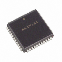
DS2141AQ+ Maxim Integrated Products, DS2141AQ+ Datasheet - Page 9

DS2141AQ+
Manufacturer Part Number
DS2141AQ+
Description
IC CONTROLLER T1 5V 44-PLCC
Manufacturer
Maxim Integrated Products
Datasheet
1.DS2141AQ.pdf
(39 pages)
Specifications of DS2141AQ+
Controller Type
T1 Controller
Interface
Parallel/Serial
Voltage - Supply
4.5 V ~ 5.5 V
Current - Supply
10mA
Operating Temperature
0°C ~ 70°C
Mounting Type
Surface Mount
Package / Case
44-LCC, 44-PLCC
Operating Supply Voltage
5 V
Supply Current (max)
10 mA
Maximum Operating Temperature
+ 70 C
Minimum Operating Temperature
0 C
Mounting Style
SMD/SMT
Lead Free Status / RoHS Status
Lead free / RoHS Compliant
TCR1: TRANSMIT CONTROL REGISTER 1 (35h)
(MSB)
ODF
SYMBOL
TLINK
TYEL
TCPT
RBSE
GB7S
TFPT
ODF
TBL
TFPT
POSITION
TCR1.7
TCR1.6
TCR1.5
TCR1.4
TCR1.3
TCR1.2
TCR1.1
TCR1.0
TCPT
NAME AND DESCRIPTION
Output Data Format.
0=bipolar data at TPOS and TNEG.
1=NRZ data at TPOS; TNEG = 0.
Transmit Framing Pass Through.
0=Ft or FPS bits sourced internally.
1=Ft or FPS bits sampled at TSER during F-bit time.
Transmit CRC Pass Through.
0=source CRC6 bits internally.
1=CRC6 bits sampled at TSER during F-bit time.
Robbed Bit Signaling Enable.
0=no signaling is inserted in any channel.
1=signaling is inserted in all channels (the TTR registers can be
used to block insertion on a channel by channel basis).
Global Bit 7 Stuffing.
0=allow the TTR registers to determine which channels
containing all zeros are to be bit 7 stuffed.
1=force bit 7 stuffing in all zero byte channels regardless of how
the TTR registers are programmed.
TLINK Select.
0=source FDL or Fs bits from TFDL register.
1=source FDL or Fs bits from the TLINK pin.
Transmit Blue Alarm.
0=transmit data normally.
1=transmit an unframed all 1's code at TPOS and TNEG.
Transmit Yellow Alarm.
0=do not transmit yellow alarm.
1=transmit yellow alarm.
RBSE
9 of 39
GB7S
TLINK
TBL
(LSB)
TYEL
DS2141A


