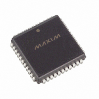
DS2141AQ+ Maxim Integrated Products, DS2141AQ+ Datasheet - Page 23

DS2141AQ+
Manufacturer Part Number
DS2141AQ+
Description
IC CONTROLLER T1 5V 44-PLCC
Manufacturer
Maxim Integrated Products
Datasheet
1.DS2141AQ.pdf
(39 pages)
Specifications of DS2141AQ+
Controller Type
T1 Controller
Interface
Parallel/Serial
Voltage - Supply
4.5 V ~ 5.5 V
Current - Supply
10mA
Operating Temperature
0°C ~ 70°C
Mounting Type
Surface Mount
Package / Case
44-LCC, 44-PLCC
Operating Supply Voltage
5 V
Supply Current (max)
10 mA
Maximum Operating Temperature
+ 70 C
Minimum Operating Temperature
0 C
Mounting Style
SMD/SMT
Lead Free Status / RoHS Status
Lead free / RoHS Compliant
Each Receive Signaling Register (RS1 to RS12) reports the incoming robbed bit signaling from eight
DS0 channels. In the ESF framing mode, there can be up to 4 signaling bits per channel (A, B, C, and D).
In the D4 framing mode, there are only 2 framing bits per channel (A and B). In the D4 framing mode,
the DS2141A will replace the C and D signaling bit positions with the A and B signaling bits from the
previous multiframe. Hence, whether the DS2141A is operated in either framing mode, the user needs
only to retrieve the signaling bits every 3 ms. The bits in the Receive Signaling Registers are updated on
multiframe boundaries so the user can utilize the Receive Multiframe Interrupt in the Receive Status
Register 2 (SR2.7) to know when to retrieve the signaling bits. The Receive Signaling Registers are
frozen and not updated during a loss of sync condition (SR1.0=1). They will contain the most recent
signaling information before the “OOF” occurred.
TS1 TO TS12: TRANSMIT SIGNALING REGISTERS (70h to 7Bh)
(MSB)
Each Transmit Signaling Register (TS1 to TS12) contains the Robbed Bit signaling for eight DS0
channels that will be inserted into the outgoing stream if enabled to do so via TCR1.4. In the ESF framing
mode, there can be up to 4 signaling bits per channel (A, B, C, and D). In the D4 framing mode, there are
only 2 framing bits per channel (A and B). On multiframe boundaries, the DS2141A will load the values
present in the Transmit Signaling Register into an outgoing signaling shift register that is internal to the
device. The user can utilize the Transmit Multiframe Interrupt in Status Register 2 (SR2.6) to know when
to update the signaling bits.
8.0 SPECIAL TRANSMIT SIDE REGISTERS
There is a set of seven registers in the DS2141A that can be used to custom tailor the data that is to be
transmitted onto the T1 line, on a channel by channel basis. Each of the 24 T1 channels can be either
forced to be transparent or to have a user defined idle code inserted into them. Each of these special
registers is defined below.
A(16)
A(24)
B(16)
B(24)
C(16)
C(24)
D(16)
D(24)
A(8)
B(8)
C(8)
D(8)
SYMBOL
D(24)
A(1)
A(15)
A(23)
D(15)
D(23)
B(15)
B(23)
C(15)
C(23)
A(7)
D(7)
B(7)
C(7)
POSITION
TS12.7
A(14)
A(22)
B(14)
B(22)
C(14)
C(22)
D(14)
D(22)
TS1.0
A(6)
B(6)
C(6)
D(6)
A(13)
A(21)
D(13)
D(21)
B(13)
B(21)
C(13)
C(21)
A(5)
B(5)
C(5)
D(5)
NAME AND DESCRIPTION
Signaling Bit D in Channel 24.
Signaling Bit A in Channel 1.
23 of 39
A(12)
A(20)
D(12)
D(20)
B(12)
B(20)
C(12)
C(20)
A(4)
D(4)
B(4)
C(4)
A(11)
A(19)
D(11)
D(19)
B(11)
B(19)
C(11)
C(19)
A(3)
D(3)
B(3)
C(3)
A(10)
A(18)
D(10)
D(18)
B(10)
B(18)
C(10)
C(18)
A(2)
D(2)
B(2)
C(2)
A(17)
B(17)
C(17)
D(17)
A(9)
D(9)
A(1)
B(1)
B(9)
C(1)
C(9)
D(1)
(LSB)
TS11 (7A)
TS12 (7B)
TS10 (79)
TS1 (70)
TS2 (71)
TS3 (72)
TS4 (73)
TS5 (74)
TS6 (75)
TS7 (76)
TS8 (77)
TS9 (78)
DS2141A


