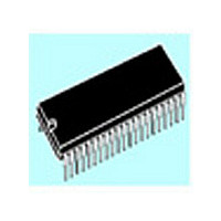
ST72T774J9B1 STMicroelectronics, ST72T774J9B1 Datasheet - Page 22

ST72T774J9B1
Manufacturer Part Number
ST72T774J9B1
Description
Manufacturer
STMicroelectronics
Datasheet
1.ST72T774J9B1.pdf
(144 pages)
Specifications of ST72T774J9B1
Cpu Family
ST7
Device Core Size
8b
Frequency (max)
24MHz
Interface Type
I2C/USB
Program Memory Type
EPROM
Program Memory Size
60KB
Total Internal Ram Size
1KB
# I/os (max)
31
Number Of Timers - General Purpose
1
Operating Supply Voltage (typ)
5V
Operating Supply Voltage (max)
5.5V
Operating Supply Voltage (min)
4V
On-chip Adc
1-chx8-bit
On-chip Dac
1-chx8-bit
Instruction Set Architecture
CISC
Operating Temp Range
0C to 70C
Operating Temperature Classification
Commercial
Mounting
Through Hole
Pin Count
42
Package Type
SPDIP
Lead Free Status / Rohs Status
Specific Sites Compliant
Available stocks
Company
Part Number
Manufacturer
Quantity
Price
Part Number:
ST72T774J9B1
Manufacturer:
ST
Quantity:
20 000
ST72774/ST727754/ST72734
3.3 INTERRUPTS
The ST727x4 may be interrupted by one of two
different methods: maskable hardware interrupts
as listed in
interrupt
flowchart is shown in
The maskable interrupts must be enabled in order
to be serviced. However, disabled interrupts can
be latched and processed when they are enabled.
When an interrupt has to be serviced, the PC, X, A
and CC registers are saved onto the stack and the
interrupt mask (I bit of the Condition Code
Register) is set to prevent additional interrupts.
The Y register is not automatically saved.
The PC is then loaded with the interrupt vector of
the interrupt to service and the interrupt service
routine runs (refer to Table 6, “Interrupt Mapping,”
on page 24 for vector addresses). The interrupt
service routine should finish with the IRET
instruction which causes the contents of the
registers to be recovered from the stack and
normal processing to resume. Note that the I bit is
then cleared if and only if the corresponding bit
stored in the stack is zero.
Though many interrupts can be simultaneously
pending, a priority order is defined (see Table 6,
“Interrupt Mapping,” on page 24). The RESET pin
has the highest priority.
If the I bit is set, only the TRAP interrupt is enabled.
All interrupts allow the processor to leave the
WAIT low power mode.
Software Interrupt. The software interrupt is the
executable instruction TRAP. The interrupt is
recognized
executed, regardless of the state of the I bit. When
the interrupt is recognized, it is serviced according
to the flowchart on
22/144
(TRAP).
Table 6
when
Figure
and a non-maskable software
the
The
Figure
13.
TRAP
Interrupt
13.
instruction
processing
is
ITA, ITB interrupts. The ITA (PD3), ITB (PD4),
pins can generate an interrupt when a falling edge
occurs on these pins, if these interrupts are
enabled with the ITAITE, ITBITE bits respectively
in the miscellaneous register and the I bit of the CC
register is reset. When an enabled interrupt
occurs, normal processing is suspended at the
end of the current instruction execution. It is then
serviced according to the flowchart on
Software in the ITA or ITB service routine must
reset the cause of this interrupt by clearing the
ITALAT, ITBLAT or ITAITE, ITBITE bits in the
miscellaneous register.
Peripheral
interrupt flags are able to cause an interrupt when
they are active if both the I bit of the CC register is
reset and if the corresponding enable bit is set. If
either of these conditions is false, the interrupt is
latched and thus remains pending.
The interrupt flags are located in the status
register. The Enable bits are in the control register.
When an enabled interrupt occurs, normal
processing is suspended at the end of the current
instruction execution. It is then serviced according
to the flowchart on
The general sequence for clearing an interrupt is
an access to the status register while the flag is set
followed by a read or write of an associated
register. Note that the clearing sequence resets
the internal latch. A pending interrupt (i.e. waiting
for being enabled) will therefore be lost if the clear
sequence is executed.
Interrupts.
Figure
13.
Different
Figure
peripheral
13.


