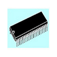
ST72T774J9B1 STMicroelectronics, ST72T774J9B1 Datasheet - Page 62

ST72T774J9B1
Manufacturer Part Number
ST72T774J9B1
Description
Manufacturer
STMicroelectronics
Datasheet
1.ST72T774J9B1.pdf
(144 pages)
Specifications of ST72T774J9B1
Cpu Family
ST7
Device Core Size
8b
Frequency (max)
24MHz
Interface Type
I2C/USB
Program Memory Type
EPROM
Program Memory Size
60KB
Total Internal Ram Size
1KB
# I/os (max)
31
Number Of Timers - General Purpose
1
Operating Supply Voltage (typ)
5V
Operating Supply Voltage (max)
5.5V
Operating Supply Voltage (min)
4V
On-chip Adc
1-chx8-bit
On-chip Dac
1-chx8-bit
Instruction Set Architecture
CISC
Operating Temp Range
0C to 70C
Operating Temperature Classification
Commercial
Mounting
Through Hole
Pin Count
42
Package Type
SPDIP
Lead Free Status / Rohs Status
Specific Sites Compliant
Available stocks
Company
Part Number
Manufacturer
Quantity
Price
Part Number:
ST72T774J9B1
Manufacturer:
ST
Quantity:
20 000
ST72774/ST727754/ST72734
SYNC PROCESSOR (SYNC) (Cont’d)
4.4.6.3 Detecting Signal Polarity
The Sync Processor provides two ways for
checking input signal polarity by polling the latches
or using the 5-bit up/down counter.
Polling check
– HSYNCI polarity detection:
– VSYNCI Polarity Detection
5-bit Up/Down Counter Check
for HSYNCI Polarity
This method involves the internal 5-bit up/down
counter.
The counter value (CV4-CV0 bits) is updated with
the 5-bit counter value at every detected edge on
the signal monitored.
It is incremented when the signal is high, otherwise
it is decremented.
– Start the detection phase:
– Software checks the counter value (CV4-CV0)
In case of a composite incoming signal, the
software just has to check that the VSYNCO
period and polarity are stable.
62/144
after an interrupt (with the signal internally con-
nected or ICAP2) or by polling (timeout 150µs).
These bits are directly connected to the 5-bit
Up/Down counter.
UPLAT=1/ DOWNLAT=0 HSYNCI polarity<0
UPLAT=0/ DOWNLAT=1 HSYNCI polarity>0
– VOP bit (VSYNCO polarity control) in MCR
The delay between VSYNCI polarity changes
and the VPOL bit typically toggles within 4
msecs. The polarity detector includes an
integrator to filter possible incoming VSYNCI
glitches.
Initialize the 5-bit counter: write '00000' in the
CCR register (CV4-CV0 bits).
Select normal mode on falling edge:
Positive polarity: The counter value < 1Fh.
Negative polarity: The counter value =1Fh on
the falling edge.
– VPOL bit (VSYNCO polarity) in POLR and
UPLAT/DWNLAT bits in LATR register
LCV1/LCV0 = 0 in the CCR register.
4.4.6.4 Extracting VSYNCO from CSYNCI
In case of composite sync, the Vertical sync output
signal is extracted with the 5-bit up/down counter.
Initially,
component pulse is automatically determined by
hardware which defines a threshold for the 5-bit
counter with a possible user-defined tolerance.
The circuit then monitors for any incoming period
greater than this previously captured value. This is
then processed as the VSYNCO signal.
To use the Vsync extractor, the following steps are
necessary:
– Detection of a composite sync signal:
– Defining a threshold:
– Starting the VSYNCO hardware extraction
Note:
The extracted VSYNCO signal always has
negative polarity.
mode:
When the UPLAT and DOWNLAT bits in LATR
register are set, a composite sync signal or a
HSYNCI polarity change is detected.
If these bits are stable during two subsequent
ICAP2 interrupt, the composite sync signal is
stable.
Select the normal mode (LCV1/LCV0=0 in the
CCR register).
Initialize the counter capture CV4-CV0 to 0.
This automatically measures the HSYNCI pulse
width. It defines a threshold in the CV4-CV0 bits
used by the 5-bit up/down counter.
It also allows to check the HSYNCI polarity
(refer to the “5-bit Up/Down Counter Check”
paragraph.
If a user-defined tolerance is to be added, then
an updated value should be written in the CCR
register (CV4-CV0 bits).
In a composite sync signal, Hsync and Vsync
always have the same polarity.
According to the Composite sync polarity, select
the extraction mode (LCV1/LCV0 in CCR
register) and rewrite the counter if necessary.
Negative polarity: minimum threshold (00h)
Positive polarity: maximum threshold (1Fh)
the
width
of
an
Horizontal
Sync


