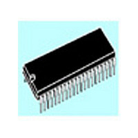
ST72T774J9B1 STMicroelectronics, ST72T774J9B1 Datasheet - Page 76

ST72T774J9B1
Manufacturer Part Number
ST72T774J9B1
Description
Manufacturer
STMicroelectronics
Datasheet
1.ST72T774J9B1.pdf
(144 pages)
Specifications of ST72T774J9B1
Cpu Family
ST7
Device Core Size
8b
Frequency (max)
24MHz
Interface Type
I2C/USB
Program Memory Type
EPROM
Program Memory Size
60KB
Total Internal Ram Size
1KB
# I/os (max)
31
Number Of Timers - General Purpose
1
Operating Supply Voltage (typ)
5V
Operating Supply Voltage (max)
5.5V
Operating Supply Voltage (min)
4V
On-chip Adc
1-chx8-bit
On-chip Dac
1-chx8-bit
Instruction Set Architecture
CISC
Operating Temp Range
0C to 70C
Operating Temperature Classification
Commercial
Mounting
Through Hole
Pin Count
42
Package Type
SPDIP
Lead Free Status / Rohs Status
Specific Sites Compliant
Available stocks
Company
Part Number
Manufacturer
Quantity
Price
Part Number:
ST72T774J9B1
Manufacturer:
ST
Quantity:
20 000
ST72774/ST727754/ST72734
TIMING MEASUREMENT UNIT (Cont’d)
The H_V bit selects horizontal or vertical
measurement. This selection should be made prior
to starting the measurement by setting the START
bit. This bit is set by software but only cleared by
hardware at the end of the measurement.
When the measurement is finished (rising edge of
AV, horizontal or vertical sync signals), the results
(T1,T2) are transferred into the corresponding
registers (H1,H2) or (V1,V2).
Note: The values of the H1/H2 or V1/V2 registers are
4.5.3.1 Horizontal Measurement
When the H_V bit = 1, and when the START bit is
set by software, the measurement starts after the
next vertical sync pulse. The TMU searches the
minimum values of H1 and H2 until the rising edge
of the next following vertical sync pulse. The
START bit is then cleared by hardware.
Figure 48. Horizontal Measurement
Figure 49. Vertical Measurement
76/144
– Obtain the minimum number of horizontal
sync output pulses (V2) between the last fall-
ing edge of the active video input (AV) and the
rising edge of the vertical sync signal (VSYN-
CO or VFBACK) during two 2 consecutive
frames.
HSYNCO or
HFBACK
AV
VSYNCO or
VFBACK
AV
available only at the end of a measurement (after
the START bit has been cleared).
H1 and H2 measured in oscillator clock periods
Note: HSYNCO or HFBACK must be positive.
V1 and V2 measured in horizontal pulses
Note: VSYNCO or VFBACK must be positive.
H1
V1
The values of the H1 and H2 registers are
available only at the end of a measurement, in
other words when the START bit is at 0.
4.5.3.2 Vertical Measurement
When the H_V bit = 0 and, when the START bit is
set by software, the TMU measures the minimum
V1 and V2 values during 2 consecutive vertical
frames. The START bit is then cleared by
hardware.
4.5.3.3 Special cases
– If an overflow of the counter occurs during any of
– If the AV signal is always low (no active video),
– If T1
– If T2 0 (AV still high when the rising edge of the
Note: Refer to Application Note AN1183 for further de-
the measurements, the measured T1 or T2 val-
ues will be 7FFh.
the measured T1 or T2 values will also be 7FFh.
of the sync signal occurs), the measured T1 val-
ue will be fixed to 1.
sync signal occurs), a specific T2 value will be re-
turned.
tails.
0 (AV already high when the falling edge
H2
V2


