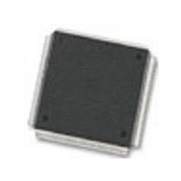
MC68376BAMFT20 Freescale Semiconductor, MC68376BAMFT20 Datasheet - Page 83

MC68376BAMFT20
Manufacturer Part Number
MC68376BAMFT20
Description
Manufacturer
Freescale Semiconductor
Datasheet
1.MC68376BAMFT20.pdf
(434 pages)
Specifications of MC68376BAMFT20
Cpu Family
68K/M683xx
Device Core
ColdFire
Device Core Size
32b
Frequency (max)
20MHz
Interface Type
QSPI/SCI
Program Memory Type
ROM
Program Memory Size
8KB
Total Internal Ram Size
7.5KB
# I/os (max)
18
Number Of Timers - General Purpose
2
Operating Supply Voltage (typ)
5V
Operating Supply Voltage (max)
5.25V
Operating Supply Voltage (min)
4.75V
On-chip Adc
16-chx10-bit
Instruction Set Architecture
RISC
Operating Temp Range
-40C to 125C
Operating Temperature Classification
Automotive
Mounting
Surface Mount
Pin Count
160
Package Type
PQFP
Lead Free Status / Rohs Status
Not Compliant
Available stocks
Company
Part Number
Manufacturer
Quantity
Price
Company:
Part Number:
MC68376BAMFT20
Manufacturer:
FREESCAL
Quantity:
245
- Current page: 83 of 434
- Download datasheet (7Mb)
5.3.2 Clock Synthesizer Operation
MC68336/376
USER’S MANUAL
*
RESISTANCE AND CAPACITANCE BASED ON A TEST CIRCUIT CONSTRUCTED WITH A KDS041-18 4.194 MHz CRYSTAL.
SPECIFIC COMPONENTS MUST BE BASED ON CRYSTAL TYPE. CONTACT CRYSTAL VENDOR FOR EXACT CIRCUIT.
To generate a reference frequency using the crystal oscillator, a reference crystal
must be connected between the EXTAL and XTAL pins. Typically, a 4.194 MHz crystal
is used, but the frequency may vary between 1 and 6 MHz. Figure 5-3 shows a typical
circuit.
If a fast reference frequency is provided to the PLL from a source other than a crystal,
or an external system clock signal is applied through the EXTAL pin, the XTAL pin
must be left floating.
When an external system clock signal is applied (MODCLK = 0 during reset), the PLL
is disabled. The duty cycle of this signal is critical, especially at operating frequencies
close to maximum. The relationship between clock signal duty cycle and clock signal
period is expressed as follows:
V
either a crystal or an externally supplied reference frequency. A separate power
source increases MCU noise immunity and can be used to run the clock when the
MCU is powered down. A quiet power supply must be used as the V
equate external bypass capacitors should be placed as close as possible to the
V
signal is applied and the PLL is disabled, V
ply. Refer to the SIM Reference Manual (SIMRM/AD) for more information regarding
system clock power supply conditioning.
DDSYN
DDSYN
is used to power the clock circuits when the system clock is synthesized from
pin to assure a stable operating frequency. When an external system clock
----------------------------------------------------------------------------------------------------------------------------------------------------------------------- -
50% Percentage Variation of External Clock Input Duty Cycle
–
Figure 5-3 System Clock Oscillator Circuit
Minimum External Clock High/Low Time
Minimum External Clock Period
SYSTEM INTEGRATION MODULE
C1
27 pF*
C2
27 pF*
V
SS
R1
1.5 k
DDSYN
R2
1 M
should be connected to the V
EXTAL
XTAL
=
DDSYN
source. Ad-
MOTOROLA
32 OSCILLATOR 4M
DD
sup-
5-5
Related parts for MC68376BAMFT20
Image
Part Number
Description
Manufacturer
Datasheet
Request
R
Part Number:
Description:
Manufacturer:
Freescale Semiconductor, Inc
Datasheet:
Part Number:
Description:
Manufacturer:
Freescale Semiconductor, Inc
Datasheet:
Part Number:
Description:
Manufacturer:
Freescale Semiconductor, Inc
Datasheet:
Part Number:
Description:
Manufacturer:
Freescale Semiconductor, Inc
Datasheet:
Part Number:
Description:
Manufacturer:
Freescale Semiconductor, Inc
Datasheet:
Part Number:
Description:
Manufacturer:
Freescale Semiconductor, Inc
Datasheet:
Part Number:
Description:
Manufacturer:
Freescale Semiconductor, Inc
Datasheet:
Part Number:
Description:
Manufacturer:
Freescale Semiconductor, Inc
Datasheet:
Part Number:
Description:
Manufacturer:
Freescale Semiconductor, Inc
Datasheet:
Part Number:
Description:
Manufacturer:
Freescale Semiconductor, Inc
Datasheet:
Part Number:
Description:
Manufacturer:
Freescale Semiconductor, Inc
Datasheet:
Part Number:
Description:
Manufacturer:
Freescale Semiconductor, Inc
Datasheet:
Part Number:
Description:
Manufacturer:
Freescale Semiconductor, Inc
Datasheet:
Part Number:
Description:
Manufacturer:
Freescale Semiconductor, Inc
Datasheet:
Part Number:
Description:
Manufacturer:
Freescale Semiconductor, Inc
Datasheet:


