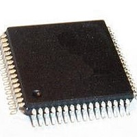
PSB 2132 H V2.2 Infineon Technologies, PSB 2132 H V2.2 Datasheet - Page 16

PSB 2132 H V2.2
Manufacturer Part Number
PSB 2132 H V2.2
Description
IC CODEC FILTER 2CHAN MQFP-64
Manufacturer
Infineon Technologies
Series
SICOFI®r
Datasheet
1.PSB_2132_H_V2.2.pdf
(69 pages)
Specifications of PSB 2132 H V2.2
Package / Case
64-QFP
Function
CODEC Filter
Interface
IOM-2 PCM, SPI
Number Of Circuits
2
Voltage - Supply
5V
Current - Supply
18mA
Power (watts)
90mW
Mounting Type
Surface Mount
Includes
Level Metering Function, Tone Generation
Number Of Adc Inputs
2
Number Of Dac Outputs
2
Interface Type
Serial
Operating Supply Voltage
5 V
Maximum Operating Temperature
+ 70 C
Mounting Style
SMD/SMT
Minimum Operating Temperature
0 C
Number Of Channels
2
Snr
35.4 dB
Supply Current
40 mA
Lead Free Status / RoHS Status
Lead free / RoHS Compliant
Operating Temperature
-
Lead Free Status / RoHS Status
Lead free / RoHS Compliant, Lead free / RoHS Compliant
Other names
PSB2132HV2.2XT
SP000007696
SP000007696
Hardware Reference Manual
22
23
24
25
26
27
28
29
30
31
32
Pin Symbol Type Function
RESET#
V
DCL
FSC
BCL
NU
DU
DD
NU
DD
DU
DDD
state
state
state
state
I/O/
I/O/
I/O/
I/O/
tri-
tri-
tri-
tri-
I
I
I
I
I
Master Clock Input
1536 kHz signal must be applied for any operation. DCL,
BCL, and FSC must be synchronous.
Reset Input
Forces the device to default setting mode; active low.
Digital Supply Voltage
+5 V supply for digital circuits (use 100 nF blocking cap.).
None Usable
Leave unconnected.
IOM-2 Data Upstream
Interface together with Pin 30. Both pins must be
connected together. Transmits or receives PCM data in
8-bit bursts every 125 µs. With push-pull resistor.
IOM-2 Data Downstream
Interface together with Pin 29. Both pins must be
connected together. Transmits or receives PCM data in
8-bit bursts every 125 µs. With push-pull resistor.
None Usable
Leave unconnected.
IOM-2 Data Downstream
Interface together with Pin 27. Both pins must be
connected together. Transmits or receives PCM data in
8-bit bursts every 125 µs. With push-pull resistor.
IOM-2 Data Upstream
Interface together with Pin 26. Both pins must be
connected together. Transmits or receives PCM data in
8-bit bursts every 125 µs. With push-pull resistor.
Frame Synchronization Clock
8 kHz; reference for individual time slots, indicates start of
PCM frame; DCL, BCL and FSC must be synchronous.
IOM-2 Bit Clock
Determines rate at which PCM data is shifted into or out
of PCM-ports. BCL, DCL, and FSC must be synchronous.
If C-MODE = 0 in XR6, single clocking mode is used; 768
kHz must be applied to BCL.
If C-MODE = 1 in XR6, double clocking mode is used;
1536 kHz must be applied to BCL.
The data rate at the PCM ports remains 768 kbit/s.
7
Pin Descriptions
PSB 2132
2001-02-20
both
both
both
both
both
both
both
both
both
Ch.


