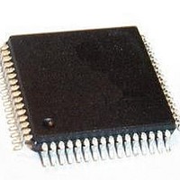
PSB 2132 H V2.2 Infineon Technologies, PSB 2132 H V2.2 Datasheet - Page 17

PSB 2132 H V2.2
Manufacturer Part Number
PSB 2132 H V2.2
Description
IC CODEC FILTER 2CHAN MQFP-64
Manufacturer
Infineon Technologies
Series
SICOFI®r
Datasheet
1.PSB_2132_H_V2.2.pdf
(69 pages)
Specifications of PSB 2132 H V2.2
Package / Case
64-QFP
Function
CODEC Filter
Interface
IOM-2 PCM, SPI
Number Of Circuits
2
Voltage - Supply
5V
Current - Supply
18mA
Power (watts)
90mW
Mounting Type
Surface Mount
Includes
Level Metering Function, Tone Generation
Number Of Adc Inputs
2
Number Of Dac Outputs
2
Interface Type
Serial
Operating Supply Voltage
5 V
Maximum Operating Temperature
+ 70 C
Mounting Style
SMD/SMT
Minimum Operating Temperature
0 C
Number Of Channels
2
Snr
35.4 dB
Supply Current
40 mA
Lead Free Status / RoHS Status
Lead free / RoHS Compliant
Operating Temperature
-
Lead Free Status / RoHS Status
Lead free / RoHS Compliant, Lead free / RoHS Compliant
Other names
PSB2132HV2.2XT
SP000007696
SP000007696
33
34
35
36
37
38
39
40
41
42
43
44
45
46
47
48
49
50
51
52
53
Hardware Reference Manual
Pin Symbol Type Function
GNDA1
SO1_1
SO1_0
SO2_0
SO2_1
SB1_2
SB1_1
SB1_0
SB2_0
SB2_1
SB2_2
RGEN
V
INT12
SI1_1
SI1_0
SI2_0
SI2_1
V
V
V
DDA12
OUT1
OUT2
IN1
I/O
I/O
I/O
I/O
I/O
I/O
O
O
O
O
O
O
O
O
I
I
I
I
I
I
I
Ring Generator Output
Configurable output clock (2 … 28 ms) synchronous to
DCL. Square-wave signal with duty cycle 1:1.
Interrupt Output, Channels 1 and 2
Active high.
Signaling Input Channel 1, Pin 1
Signaling Input Channel 1, Pin 0
Bi-directional Signaling, Channel 1 Pin 2
Bi-directional Signaling, Channel 1 Pin 1
Bi-directional Signaling, Channel 1 Pin 0
Signaling Output, Channel 1, Pin 1
Signaling Output, Channel 1, Pin 0
Signaling Output, Channel 2, Pin 0
Signaling Output, Channel 2, Pin 1
Bi-directional Signaling, Channel 2 Pin 0
Bi-directional Signaling, Channel 2 Pin 1
Bi-directional Signaling, Channel 2 Pin 2
Signaling Input, Channel 2, Pin 0
Signaling Input, Channel 2, Pin 1
Analog Voice (Voltage) Input, Channel 1
Requires a coupling capacitor >39 nF to the SLIC.
Analog Ground, Channel 1
Not internally connected to GNDD or GNDA2 or GNDA.
Analog Voice (Voltage) Output, Channel 1
Requires a coupling capacitor to the SLIC. The capacitor
value depends on the SLIC’s input impedance. (See
Chapter 5.1, "Analog Interface" on page 25).
Analog Supply Voltage, Channels 1 and 2
+5 V (100 nF blocking capacitor required).
Analog Voice (Voltage) Output, Channel 2
Requires a coupling capacitor to the SLIC. The capacitor
value depends on the SLIC’s input impedance. (See
Chapter 5.1, "Analog Interface" on page 25).
8
Pin Descriptions
PSB 2132
2001-02-20
both
both
both
Ch.
1
1
1
1
1
1
1
2
2
2
2
2
2
2
1
1
1
2


