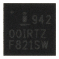
ISL94200IRZ Intersil, ISL94200IRZ Datasheet - Page 18

ISL94200IRZ
Manufacturer Part Number
ISL94200IRZ
Description
IC MULTI LI-ION OC PROT 24-QFN
Manufacturer
Intersil
Datasheet
1.ISL94200IRZ.pdf
(28 pages)
Specifications of ISL94200IRZ
Function
Over/Under Voltage Protection
Battery Type
Lithium-Ion (Li-Ion)
Voltage - Supply
5 V ~ 10 V
Operating Temperature
-40°C ~ 85°C
Mounting Type
Surface Mount
Package / Case
24-VFQFN Exposed Pad
Lead Free Status / RoHS Status
Lead free / RoHS Compliant
Available stocks
Company
Part Number
Manufacturer
Quantity
Price
Company:
Part Number:
ISL94200IRZ
Manufacturer:
Intersil
Quantity:
20
WKUP Pin Operation
There are two ways to design a wake up of the ISL94200. In
an active LOW connection (WKPOL = “0” - default), the
device wakes up when a charger is connected to the pack.
This pulls the WKUP pin low when compared to a reference
based on the V
(WKPOL = ‘1’) the device wakes up when the WKUP pin is
pulled high by a connection through an external switch.
Protection Functions
In the default recommended condition, the ISL94200
automatically responds to discharge overcurrent, discharge
short circuit, charge overcurrent, internal over-temperature,
and external over-temperature conditions. The designer can
set optional over-ride conditions that allow the response to
be dictated by the microcontroller. These are discussed
below.
OVERCURRENT SAFETY FUNCTIONS
The ISL94200 continually monitors the discharge current by
monitoring the voltage at the CSENSE and DSENSE pins. If
that voltage exceeds a selected value for a time exceeding a
selected delay, then the device enters an overcurrent or short
circuit protection mode. In these modes, the ISL94200
automatically turns off both power FETs and hence prevents
current from flowing through the terminals P+ and P-.
The voltage thresholds and the response times of the
overcurrent protection circuits are selectable for discharge
overcurrent, charge overcurrent, and discharge short circuit
conditions. The specific settings are determined by bits in
the Discharge Set Configuration Register (ADDR:05H) (refer
to Table 6) and the Charge/Time Scale Configuration Scale
Register (ADDR:06H) (refer to Table 7). In addition, refer to
“Registers” on page 12.
V
FIGURE 3. WAKE UP CONTROL CIRCUITS
ISL94200
CELL1
(STATUS)
WAKE UP
CIRCUITS
CELL1
WKUP
voltage. In an active HIGH connection
(CONTROL)
* Internal resistor
only connected when
WKPOL = 1.
18
WKPOL
230k*
5V
VSS
WKUP
ISL94200
In an overcurrent condition, the ISL94200 automatically turns
off the voltage on CFET and DFET pins. The DFET output
drives the discharge FET gate low, turning off the FET quickly.
The CFET output turns off and allows the gate of the charge
FET to be pulled low through a resistor.
By turning off the FETs the ISL94200 prevents damage to the
battery pack caused by excessive current into or out of the cells
(as in the case of a faulty charger or short-circuit condition).
When the ISL94200 detects a discharge overcurrent condition,
both power FETs are turned off and the DOC bit is set. (When
the FETs are turned off, the DFET and CFET bits are also
reset.) The automatic response to overcurrent during discharge
is prevented by setting the DENOCD bit to “1”. The external
microcontroller can turn on the FETs at any time to recover from
this condition, but it would usually turn on the load monitor
function (by setting the LDMONEN bit) and monitor the LDFAIL
bit to detect that the overcurrent condition has been removed.
When the ISL94200 detects a discharge short circuit condition,
both power FETs are turned off and DSC bit is set. (When the
FETs are turned off, the DFET and CFET bits are also reset.)
The automatic response to short circuit during discharge is
prevented by setting the DENSCD bit to “1”. The external
microcontroller can turn on the FETs at any time to recover from
this condition, but it would usually turn on the load monitor
function (by setting the LDMONEN bit) and monitor the LDFAIL
bit to detect that the overcurrent condition has been removed.
When the ISL94200 detects a charge overcurrent condition,
both power FETs are turned off and COC bit is set. (When the
FETs are turned off, the DFET and CFET bits are also reset.)
The automatic response to overcurrent during discharge is
prevented by setting the DENOCC bit to “1”. The external
microcontroller can turn on the FETs at any time to recover from
this condition, but it would usually wait to do this until the cell
voltages are not over charged and that the overcurrent
condition has been removed. Or, the microcontroller could wait
until the pack is removed from the charger and then
re-attached.
An alternative method of providing the protection function, if
desired by the designer, is to turn off the automatic safety
response. In this case, the ISL94200 devices still monitor the
conditions and set the status bits, but take no action in
overcurrent or short circuit conditions. Safety of the pack
depends, instead, on the microcontroller to send commands to
the ISL94200 to turn off the FETs.
To facilitate a microcontroller response to an overcurrent
condition, especially if the microcontroller is in a low power
state, a charge overcurrent flag (COC), a discharge overcurrent
flag (DOC), or the short circuit flag (DSC) being set causes the
ISL94200 TEMP3V output to turn on and pull high (see
Figure 5). This output can be used as an external interrupt by
the microcontroller to wake-up quickly to handle the overcurrent
condition.
July 3, 2008
FN6718.0


