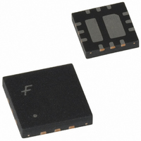
FAN5608HMPX Fairchild Semiconductor, FAN5608HMPX Datasheet - Page 8

FAN5608HMPX
Manufacturer Part Number
FAN5608HMPX
Description
IC LED DRIVR WHITE BCKLGT 12-MLP
Manufacturer
Fairchild Semiconductor
Type
Backlight, White LED (Serial Interface)r
Datasheet
1.FAN5608DHMPX.pdf
(15 pages)
Specifications of FAN5608HMPX
Topology
PWM, Step-Up (Boost)
Number Of Outputs
2
Internal Driver
Yes
Type - Primary
Backlight
Type - Secondary
White LED
Frequency
500kHz
Voltage - Supply
2.7 V ~ 5.5 V
Voltage - Output
24V
Mounting Type
Surface Mount
Package / Case
12-MLP
Operating Temperature
-40°C ~ 85°C
Current - Output / Channel
20mA
Internal Switch(s)
Yes
Efficiency
85%
Number Of Segments
12
Operating Supply Voltage
2.7 V to 5.5 V
Maximum Supply Current
0.1 mA
Maximum Operating Temperature
+ 85 C
Mounting Style
SMD/SMT
Minimum Operating Temperature
- 40 C
Lead Free Status / RoHS Status
Lead free / RoHS Compliant
Other names
FAN5608HMPXTR
FAN5608HMPX_NL
FAN5608HMPX_NLTR
FAN5608HMPX_NLTR
FAN5608HMPX_NL
FAN5608HMPX_NLTR
FAN5608HMPX_NLTR
8
FAN5608
Applications Information
Inductor Selection
The inductor is one of the main components required by the
boost converter to store energy. The amount of energy stored
in the inductor and transferred to the load is controlled by the
regulator using PWM and pulse skipping techniques.
FAN5608 operates the inductor in discontinuous conduction
mode in most cases.
To ensure proper operation of the current regulator over the
entire range of conditions, the inductor should be selected
based on the maximum required power (P
mum input voltage (V
where units of L, V
respectively F = 0.4 is a factor depending upon the FAN5608
architecture.
The above relation is applicable up to P
L = 4.3
decreases due to the resistive loss in the switching Power
FET. Using L = 4.3
20mA (P
constant 20mA current through LEDs. The inductor L =
4.3 H ensures proper operation for 2 x 4 white LEDs with
20mA at 3.5V for V
For any lighter load or higher V
increased to improve the system efficiency. Application
examples are given in Figure 1 through Figure 4.
The peak current in the inductor is:
which gives the maximum rated current for the inductor. For
L = 4.3 H, T
inductor saturation current should be at least 1A.
Capacitor Selection
Low ESR capacitors should be used to minimize the input
and output ripple voltage. Use of C
C
capacitor is recommended.
OUT
= 4.7 F/25V type X5R/X7R multi layer ceramic
OUT
or greater. At lower inductor value the efficiency
= 800mW) requires V
ON_Max
I
=
IN
IN
T
-------------------------------------------------- -
IN
L
, and P
> 2.8V.
ON_Max
= 1.25 S and V
and increasing the load to 12 LED x
).
--------------------------- -
V
IN
P
OUT
OUT
L
2
V
IN
are in H, Volt, and Watt,
IN
IN_Max
, the inductance can be
IN
F
= 4.7 F/6.3V and
> 3.5V to maintain a
OUT
IN_Max
OUT
= 0.6W and
) and the mini-
= 4.2V, the
A larger value input capacitor placed as close as possible to
FAN5608 may be needed to reduce the input voltage ripple
in noise sensitive applications. An additional LC filter
between the battery and the FAN5608 input can help to fur-
ther reduces the battery ripple to the level required by a par-
ticular application.
PCB Layout Consideration
The FAN5608 is available in both a single Die Attach Pad
(DAP) and a dual DAP package. In the single DAP package,
DAP is connected to GND. In the dual DAP package, one
DAP is connected to GND and another to V
is not necessary to provide any external connection to the
DAPs. Since the internal power dissipation is low, both the
3x3mm and 4x4mm MLP packages are capable of dissipat-
ing maximum power, without providing any PCB land pat-
tern. When viewing the bottom of the package of a single
DAP device, a single exposed metal island can be seen; when
viewing the bottom of the package of a dual DAP device, two
electrically isolated exposed metal islands can be seen.
Preliminary Data Sheet
REV. 0.8.3 5/29/03
OUT
, therefore it


