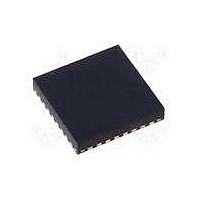
MAX15048ETJ+ Maxim Integrated Products, MAX15048ETJ+ Datasheet - Page 10

MAX15048ETJ+
Manufacturer Part Number
MAX15048ETJ+
Description
IC CTRLR PWM STP-DN TRIPL 32WQFN
Manufacturer
Maxim Integrated Products
Datasheet
1.MAX15048ETJ.pdf
(31 pages)
Specifications of MAX15048ETJ+
Applications
Power Supply Controller, Sequencer
Voltage - Supply
4.7 V ~ 23 V
Current - Supply
6mA
Operating Temperature
-40°C ~ 85°C
Mounting Type
Surface Mount
Package / Case
32-WQFN Exposed Pad
Number Of Outputs
3
Output Voltage
5 V
Input Voltage
4.7 V to 23 V
Supply Current
6 mA
Switching Frequency
200 KHz
Mounting Style
SMD/SMT
Maximum Operating Temperature
+ 85 C
Minimum Operating Temperature
- 40 C
Lead Free Status / RoHS Status
Lead free / RoHS Compliant
Voltage - Input
-
Lead Free Status / Rohs Status
Lead free / RoHS Compliant
Triple-Output Buck Controllers
with Tracking/Sequencing
10
_____________________________________________________________________________________
PIN
10
11
1
2
3
4
5
6
7
8
9
COMP2
PGND2
DREG2
NAME
SGND
BST2
DH2
DL2
EN2
LX2
FB2
RT
Oscillator Timing Resistor Connection. Connect a 15.6kI to 93.75kI resistor from RT to SGND to
program the switching frequency from 200kHz to 1.2MHz.
Analog Ground. Connect SGND and PGND_ together at one point near the input bypass capacitor
return terminal.
Controller 2 Power Ground. Connect the input filter capacitor’s negative terminal, the source of the
synchronous MOSFET, and the output filter capacitor’s return to PGND2.
Controller 2 Low-Side Gate-Driver Output. DL2 is the gate-driver output for the synchronous MOSFET.
Controller 2 Low-Side Gate-Driver Supply. Connect externally to REG through a 1I to 4.7I resistor.
Connect a minimum of 0.22FF ceramic capacitor from DREG2 to PGND2.
Controller 2 High-Side MOSFET Source Connection/Synchronous MOSFET Drain Connection.
Connect the inductor and the negative side of the boost capacitor to LX2.
Controller 2 High-Side Gate-Driver Output. DH2 drives the gate of the high-side MOSFET.
Controller 2 High-Side Gate-Driver Supply. Connect a 0.1FF ceramic capacitor from BST2 to LX2.
Controller 2 Enable/Tracking Input. See Figure 2. When tracking (MAX15048), connect the same
resistive voltage-divider used for FB2 from output 1 to EN2 to SGND for coincident tracking. Connect
EN2 to analog ground for ratiometric tracking. When sequencing (MAX15049), EN2 must be above
0.6V for PWM controller 2 to start.
Controller 2 Feedback Regulation Point. Connect to the center tap of a resistive voltage-divider from
the converter output to SGND to set the output voltage. The FB2 voltage regulates to 0.6V (typ).
Controller 2 Transconductance Error-Amplifier Output. Connect COMP2 to the compensation
feedback network of output 2.
TOP VIEW
*EXPOSED PAD.
PGND3
DREG3
BST3
DH3
DL3
REG
LX3
IN
25
26
27
28
29
30
31
32
24
1
+
23
2
EP*
(5mm × 5mm)
22
3
MAX15048
MAX15049
TQFN
21
4
20
5
19
6
FUNCTION
18
7
17
8
16 BST1
15 EN1
14
13
12
11
10
9
FB1
COMP1
PGOOD
COMP2
FB2
EN2
Pin Configuration
Pin Description


