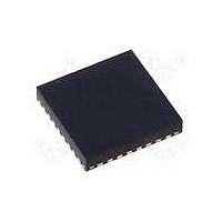
MAX15048ETJ+ Maxim Integrated Products, MAX15048ETJ+ Datasheet - Page 18

MAX15048ETJ+
Manufacturer Part Number
MAX15048ETJ+
Description
IC CTRLR PWM STP-DN TRIPL 32WQFN
Manufacturer
Maxim Integrated Products
Datasheet
1.MAX15048ETJ.pdf
(31 pages)
Specifications of MAX15048ETJ+
Applications
Power Supply Controller, Sequencer
Voltage - Supply
4.7 V ~ 23 V
Current - Supply
6mA
Operating Temperature
-40°C ~ 85°C
Mounting Type
Surface Mount
Package / Case
32-WQFN Exposed Pad
Number Of Outputs
3
Output Voltage
5 V
Input Voltage
4.7 V to 23 V
Supply Current
6 mA
Switching Frequency
200 KHz
Mounting Style
SMD/SMT
Maximum Operating Temperature
+ 85 C
Minimum Operating Temperature
- 40 C
Lead Free Status / RoHS Status
Lead free / RoHS Compliant
Voltage - Input
-
Lead Free Status / Rohs Status
Lead free / RoHS Compliant
Triple-Output Buck Controllers
with Tracking/Sequencing
In Figure 1c, when sequencing, the enable input must be
above 0.6V for each PWM controller to start. The V
outputs and EN_ inputs can be daisy-chained to gener-
ate power sequencing. See Figure 2 and the Typical
Operating Characteristics (V
Alternately, connect a resistive voltage-divider from the
voltage to be sequenced from the enable input to SGND
to set when each controller should start.
The output of the internal transconductance error ampli-
fier (COMP_) is provided for frequency compensation
(see the Compensation Design Guidelines section). FB_
is the inverting input and COMP_ is the output of the error
Figure 2. Ratiometric Tracking, Coincident Tracking (MAX15048), and Sequencing (MAX15049) Configurations
18
_____________________________________________________________________________________
EN1
V
MAX15049 Output-Voltage
IN
EN2
EN3
RATIOMETRIC
MAX15048
TRACKING
OUT_
Sequencing (EN_)
to EN_ Sequencing).
Error Amplifier
V
V
OUT1
OUT2
EN2
FB2
EN1
V
IN
OUT_
COINCIDENT
MAX15048
TRACKING
R
R
R
R
A
B
V
A
B
OUT3
EN3
FB3
amplifier. The error transamplifier has an 80dB open-
loop gain and a 10MHz GBW product. See the Typical
Operating Characteristics for a plot of gain and phase
vs. frequency.
The current-limit circuit employs a valley current-limiting
algorithm that uses the synchronous MOSFET’s on-
resistance as the current-sensing element. The current-
limit threshold is internally set at 69mV (typ). Once the
high-side MOSFET turns off, the voltage across the
current-sensing element is monitored. If this voltage
does not exceed the current-limit threshold, the high-
side MOSFET turns on normally at the start of the next
cycle. If the voltage exceeds the current-limit threshold
R
R
R
R
C
D
C
D
V
V
OUT1
OUT2
EN1
V
IN
MAX15049
Protection (Hiccup Mode)
SEQUENCING
Output Short-Circuit
EN2
EN3


