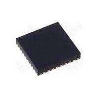
MAX15048ETJ+ Maxim Integrated Products, MAX15048ETJ+ Datasheet - Page 23

MAX15048ETJ+
Manufacturer Part Number
MAX15048ETJ+
Description
IC CTRLR PWM STP-DN TRIPL 32WQFN
Manufacturer
Maxim Integrated Products
Datasheet
1.MAX15048ETJ.pdf
(31 pages)
Specifications of MAX15048ETJ+
Applications
Power Supply Controller, Sequencer
Voltage - Supply
4.7 V ~ 23 V
Current - Supply
6mA
Operating Temperature
-40°C ~ 85°C
Mounting Type
Surface Mount
Package / Case
32-WQFN Exposed Pad
Number Of Outputs
3
Output Voltage
5 V
Input Voltage
4.7 V to 23 V
Supply Current
6 mA
Switching Frequency
200 KHz
Mounting Style
SMD/SMT
Maximum Operating Temperature
+ 85 C
Minimum Operating Temperature
- 40 C
Lead Free Status / RoHS Status
Lead free / RoHS Compliant
Voltage - Input
-
Lead Free Status / Rohs Status
Lead free / RoHS Compliant
Figure 4c. Power Modulator Gain and Phase Response (High-Quality C
The desired (compensated) rolloff follows a -20dB/
decade slope (and commensurate 90° of phase shift),
and, in this example, occurs at approximately six times
the uncompensated crossover frequency, f
example, a Type II compensator provides stable closed-
loop operation, leveraging the +20dB/decade slope of
the capacitor’s ESR zero (see Figure 4b).
The Type II compensator’s midfrequency gain (approxi-
mately 18dB shown here) is designed to compensate for
the power modulator’s attenuation at the desired cross-
over frequency, f
example, the power modulator’s inherent -20dB/decade
Figure 4b. Power Modulator (Large, Bulk C
CO
______________________________________________________________________________________
(G
E/A
-20
-40
-60
-80
40
20
+ G
0
-20
-40
-60
-80
80
60
40
20
0
MOD
= 0dB at f
OUT
|G
Triple-Output Buck Controllers
) and Type II Compensator Responses
E/A
< G
< G
|
CO
CO
MOD
E/A
|G
. In this
MOD
). In this
| ASYMPTOTE
f
|G
< G
LC
with Tracking/Sequencing
MOD
FREQUENCY (Hz)
FREQUENCY (Hz)
MOD
|
f
|G
ZERO, ESR
MOD
|
rolloff above the ESR zero (f
extend the active regulation gain bandwidth of the volt-
age regulator. As shown in Figure 4b, the net result is a
six-time increase in the regulator’s gain bandwidth while
providing greater than 75° of phase margin (the differ-
ence between G
crossover, f
Other filter schemes pose their own problems. For
instance, when choosing high-quality filter capacitor(s)
(e.g., MLCCs) and inductor, with minimal parasitics, the
inherent ESR zero can occur at a much higher frequency,
as shown in Figure 4c.
OUT
f
LC
)
f
ZERO, ESL
f
ZERO, ESR
CO
f
).
ZERO, ESL
E/A
and G
180
135
90
45
0
-45
-90
-135
-180
90
45
0
-45
-90
-135
-180
MOD
ZERO, ESR
respective phases at
) is leveraged to
23


