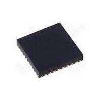
MAX15048ETJ+ Maxim Integrated Products, MAX15048ETJ+ Datasheet - Page 26

MAX15048ETJ+
Manufacturer Part Number
MAX15048ETJ+
Description
IC CTRLR PWM STP-DN TRIPL 32WQFN
Manufacturer
Maxim Integrated Products
Datasheet
1.MAX15048ETJ.pdf
(31 pages)
Specifications of MAX15048ETJ+
Applications
Power Supply Controller, Sequencer
Voltage - Supply
4.7 V ~ 23 V
Current - Supply
6mA
Operating Temperature
-40°C ~ 85°C
Mounting Type
Surface Mount
Package / Case
32-WQFN Exposed Pad
Number Of Outputs
3
Output Voltage
5 V
Input Voltage
4.7 V to 23 V
Supply Current
6 mA
Switching Frequency
200 KHz
Mounting Style
SMD/SMT
Maximum Operating Temperature
+ 85 C
Minimum Operating Temperature
- 40 C
Lead Free Status / RoHS Status
Lead free / RoHS Compliant
Voltage - Input
-
Lead Free Status / Rohs Status
Lead free / RoHS Compliant
Triple-Output Buck Controllers
with Tracking/Sequencing
Type III: Compensation when f
As previously indicated, the position of the output capac-
itor’s inherent ESR zero is critical in designing an appro-
priate compensation network. When low-ESR ceramic
output capacitors are used, the ESR zero frequency
(f
frequency (f
network is recommended (see Figure 6a).
As shown in Figure 6b, Type III compensation network
introduces two zeros and three poles into the control
loop. The error amplifier has a low-frequency pole at
the origin, two zeros, and higher frequency poles. The
locations of the zeros and poles should be such that the
phase margin peaks at f
Set the ratios of f
to get approximately 60° of phase margin at f
Whichever technique is used, it is important to place the
two zeros at or below the double pole to avoid the con-
ditional stability issue.
Figure 6a. Type III Compensation Network
Figure 6b. Type III Compensation Network Response
26
ZERO, ESR
GAIN
(dB)
_____________________________________________________________________________________
(AT ORIGIN)
1ST POLE
1ST ASYMPTOTE
(ωR
) is usually much higher than unity crossover
I
CO
C
C
R
F
I
I
)
-1
). In this case, a Type III compensation
1ST ZERO
CO
(R
2ND ASYMPTOTE
3RD ASYMPTOTE
F
C
R
R
F
-to-f
1
2
(R
V
)
-1
ωR
f
OUT_
F
CO
f
R
Z
F
I
2ND ZERO
)
C
Z
-1
(R
CO
I
V
I
C
=
REF
and f
I
)
-1
.
f
CO
f
P
2ND POLE
(R
g
P
R
M
F
5TH ASYMPTOTE
C
I
4TH ASYMPTOTE
-to-f
=
C
CO
CF
I
)
(ωR
5
-1
R
C
< f
CO
I
F
C
F
R
CF
I -1
ZERO, ESR
)
-1
COMP
equal to five:
3RD POLE
(R
F
C
CF
)
-1
ω(rad/s)
CO
.
Use the following procedure to calculate the compensa-
tion network components:
1) Select a crossover frequency, f
2) Calculate the LC double-pole frequency, f
3) Select R
4) Place a zero:
where:
5) Calculate C
Note: C
over frequency to unity, e.g. G
1V/V. The total loop gain can be expressed logarithmi-
cally as follows:
6) Place a second zero, f
7) Place a pole (
f
determining R
C
:
20 log
I
is derived by setting the total loop gain at cross-
×
C
F
20 log
I
f
Z1
R 10kI.
=
10
I
C
×
R
for a target unity-gain crossover frequency,
I
f
=
F
f
2
P1
LC
(
1
π ×
2
=
2
R
:
=
10
π ×
× π ×
1
=
2
=
2
f
C
f
π ×
π ×
2
=
2
CO
R
O
π ×
2
1
× π ×
G
F
f
π ×
2
CO
× ×
f
R
×
MOD(DC)
ZERO, ESR
π ×
R
L C
V
≤
F
Z2
1
C
IN
)
I
×
f
f
F
2
×
CO
, at or below f
f
SW
10
L C
1
Z2
1
0.75 f
1
×
C
1
× ×
E/A
×
at 0.75 f
OUT
R
L C
I
×
×
F
) at or below f
(f
R
OUT
C
CO
×
CO
F
I
×
×
LC
OUT
:
×
V
C
×
) x G
C
RAMP
I
LC
I
+
=
MOD
LC
0dB
LC
ZERO, ESR
, thereby
(f
:
CO
) =
:


