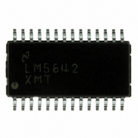
LM5642XMT/NOPB National Semiconductor, LM5642XMT/NOPB Datasheet - Page 15

LM5642XMT/NOPB
Manufacturer Part Number
LM5642XMT/NOPB
Description
IC CONV SYNC DUAL BUCK 28-TSSOP
Manufacturer
National Semiconductor
Series
PowerWise®r
Type
Step-Down (Buck)r
Datasheet
1.LM5642MTCNOPB.pdf
(28 pages)
Specifications of LM5642XMT/NOPB
Internal Switch(s)
No
Synchronous Rectifier
Yes
Number Of Outputs
2
Voltage - Output
1.3 ~ 35 V
Current - Output
20A
Frequency - Switching
375kHz
Voltage - Input
4.5 ~ 36 V
Operating Temperature
-40°C ~ 125°C
Mounting Type
Surface Mount
Package / Case
28-TSSOP
Power - Output
1.1W
For Use With
LM5642EVAL-KIT - BOARD EVALUATION LM5642
Lead Free Status / RoHS Status
Lead free / RoHS Compliant
Other names
*LM5642XMT
*LM5642XMT/NOPB
LM5642XMT
*LM5642XMT/NOPB
LM5642XMT
Available stocks
Company
Part Number
Manufacturer
Quantity
Price
Company:
Part Number:
LM5642XMT/NOPB
Manufacturer:
National Semiconductor
Quantity:
135
OVER VOLTAGE PROTECTION (OVP)
If the output voltage on either channel rises above 113% of
nominal, over voltage protection activates. Both channels will
latch off. When the OVP latch is set, the high side FET driver,
HDRVx, is immediately turned off and the low side FET driver,
LDRVx, is turned on to discharge the output capacitor through
the inductor. To reset the OVP latch, either the input voltage
must be cycled, or both channels must be switched off (both
ON/SS pins pulled low).
UNDER VOLTAGE PROTECTION (UVP) AND UV DELAY
If the output voltage on either channel falls below 80% of
nominal, under voltage protection activates. As shown in
ure
MOSFET, which will allow the UV_DELAY capacitor to
charge with 5µA (typical). If the UV_DELAY pin voltage reach-
es the 2.3V threshold both channels will latch off. UV_DELAY
will then be disabled and the UV_DELAY pin will return to 0V.
During UVP, both the high side and low side FET drivers will
be turned off. If no capacitor is connected to the UV_DELAY
pin, the UVP latch will be activated immediately. To reset the
UVP latch, either the input voltage must be cycled, or both
ON/SS pins must be pulled low. The UVP function can be
disabled by connecting the UV_DELAY pin to ground.
THERMAL SHUTDOWN
The LM5642 IC will enter thermal shutdown if the die tem-
perature exceeds 160°C. The top and bottom FETs of both
channels will be turned off immediately. In addition, both soft
start capacitors will begin to discharge through separate 5.5
µA current sinks. The voltage on both capacitors will settle to
approximately 1.1V, where it will remain until the thermal
shutdown condition has cleared. The IC will return to normal
operating mode when the die temperature has fallen to below
146°C. At this point the two soft start capacitors will begin to
5, an under-voltage event will shut off the UV_DELAY
FIGURE 5. OVP and UVP
Fig-
15
charge with their normal 2.4 µA current sources. This allows
a controlled return to normal operation, similar to the soft start
during turn-on. If the thermal shutdown condition clears be-
fore the voltage on the soft start capacitors has fallen to 1.1V,
the capacitors will first be discharged to 1.1V, and then im-
mediately begin charging back up.
OUTPUT CAPACITOR DISCHARGE
Each channel has an embedded 480Ω MOSFET with the
drain connected to the SWx pin. This MOSFET will discharge
the output capacitor of its channel if its channel is off, or the
IC enters a fault state caused by one of the following condi-
tions:
1.
2.
If an output over voltage event occurs, the HDRVx will be
turned off and LDRVx will be turned on immediately to dis-
charge the output capacitors of both channels through the
inductors.
BOOTSTRAP DIODE SELECTION
The bootstrap diode and capacitor form a supply that floats
above the switch node voltage. VLIN5 powers this supply,
creating approximately 5V (minus the diode drop) which is
used to power the high side FET drivers and driver logic.
When selecting a bootstrap diode, Schottky diodes are pre-
ferred due to their low forward voltage drop, but care must be
taken for circuits that operate at high ambient temperature.
The reverse leakage of some Schottky diodes can increase
by more than 1000x at high temperature, and this leakage
path can deplete the charge on the bootstrap capacitor, starv-
ing the driver and logic. Standard PN junction diodes and fast
rectifier diodes can also be used, and these types maintain
UVP
UVLO
20060108
www.national.com


