AD9517-2/PCBZ Analog Devices Inc, AD9517-2/PCBZ Datasheet - Page 2
AD9517-2/PCBZ
Manufacturer Part Number
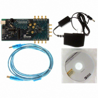
AD9517-2/PCBZ
Description
BOARD EVAL FOR AD9517-2
Manufacturer
Analog Devices Inc
Datasheet
1.AD9517-2ABCPZ-RL7.pdf
(80 pages)
Specifications of AD9517-2/PCBZ
Main Purpose
Timing, Clock Generator
Embedded
No
Utilized Ic / Part
AD9517-2
Primary Attributes
2 Inputs, 12 Outputs, 2.2GHz VCO
Secondary Attributes
CMOS, LVDS, LVPECL Output Logic, ADIsimCLK™ Graphical User Interface
Lead Free Status / RoHS Status
Lead free / RoHS Compliant


AD9517-2
TABLE OF CONTENTS
Features .............................................................................................. 1
Applications ....................................................................................... 1
General Description ......................................................................... 1
Functional Block Diagram .............................................................. 1
Revision History ............................................................................... 3
Specifications ..................................................................................... 4
Timing Diagrams ............................................................................ 15
Absolute Maximum Ratings .......................................................... 16
Power Supply Requirements ....................................................... 4
PLL Characteristics ...................................................................... 4
Clock Inputs .................................................................................. 6
Clock Outputs ............................................................................... 6
Timing Characteristics ................................................................ 7
Clock Output Additive Phase Noise (Distribution Only;
VCO Divider Not Used) .............................................................. 8
Clock Output Absolute Phase Noise (Internal VCO Used) .... 9
Clock Output Absolute Time Jitter (Clock Generation
Using Internal VCO) .................................................................. 10
Clock Output Absolute Time Jitter (Clock Cleanup
Using Internal VCO) .................................................................. 10
Clock Output Absolute Time Jitter (Clock Generation
Using External VCXO) .............................................................. 10
Clock Output Additive Time Jitter (VCO Divider
Not Used) ..................................................................................... 11
Clock Output Additive Time Jitter (VCO Divider Used) ..... 11
Delay Block Additive Time Jitter .............................................. 12
Serial Control Port ..................................................................... 12
PD , SYNC , and RESET Pins ..................................................... 13
LD, STATUS, and REFMON Pins ............................................ 13
Power Dissipation ....................................................................... 14
Thermal Resistance .................................................................... 16
Rev. B | Page 2 of 80
Pin Configuration and Function Descriptions ........................... 17
Typical Performance Characteristics ........................................... 19
Terminology .................................................................................... 25
Detailed Block Diagram ................................................................ 26
Theory of Operation ...................................................................... 27
Serial Control Port ......................................................................... 50
Thermal Performance .................................................................... 54
Control Registers ............................................................................ 55
Applications Information .............................................................. 75
Outline Dimensions ....................................................................... 78
ESD Caution................................................................................ 16
Operational Configurations ...................................................... 27
Digital Lock Detect (DLD) ....................................................... 36
Clock Distribution ..................................................................... 40
Reset Modes ................................................................................ 48
Power-Down Modes .................................................................. 49
Serial Control Port Pin Descriptions ....................................... 50
General Operation of Serial Control Port ............................... 50
The Instruction Word (16 Bits) ................................................ 51
MSB/LSB First Transfers ........................................................... 51
Control Register Map Overview .............................................. 55
Control Register Map Descriptions ......................................... 58
Frequency Planning Using the AD9517 .................................. 75
Using the AD9517 Outputs for ADC Clock Applications .... 75
LVPECL Clock Distribution ..................................................... 76
LVDS Clock Distribution .......................................................... 76
CMOS Clock Distribution ........................................................ 77
Ordering Guide .......................................................................... 78
Related parts for AD9517-2/PCBZ
Image
Part Number
Description
Manufacturer
Datasheet
Request
R

Part Number:
Description:
BOARD EVAL FOR AD9517-1
Manufacturer:
Analog Devices Inc
Datasheet:

Part Number:
Description:
12-Output Clock Generator With 2.8GHz VC
Manufacturer:
Analog Devices Inc
Datasheet:
Part Number:
Description:
12-Output Clock Generator With 2.8GHz VC
Manufacturer:
Analog Devices Inc
Datasheet:
Part Number:
Description:
12-Output Clock Generator With 2.8GHz VC
Manufacturer:
Analog Devices Inc
Datasheet:
Part Number:
Description:
12-Output Clock Generator With 2.8GHz VC
Manufacturer:
Analog Devices Inc
Datasheet:
Part Number:
Description:
12-Output Clock Generator With 2.8GHz VC
Manufacturer:
Analog Devices Inc
Datasheet:
Part Number:
Description:
12-Output Clock Generator With 2.8GHz VC
Manufacturer:
Analog Devices Inc
Datasheet:
Part Number:
Description:
BOARD EVALUATION AD9517-4
Manufacturer:
Analog Devices Inc
Datasheet:
Part Number:
Description:
12-Output Clock Generator With 2.5GHz VC
Manufacturer:
Analog Devices Inc
Datasheet:
Part Number:
Description:
12OutputClock Generator With 2.0 GHz VCO
Manufacturer:
Analog Devices Inc
Datasheet:
Part Number:
Description:
12OutputClock Generator With 1.8 GHz VCO
Manufacturer:
Analog Devices Inc
Datasheet:

Part Number:
Description:
IC CLOCK GEN 1.8GHZ VCO 48-LFCSP
Manufacturer:
Analog Devices Inc
Datasheet:
Part Number:
Description:
12-Output Clock Generator With 2.8GHz VC
Manufacturer:
Analog Devices Inc
Datasheet:
Part Number:
Description:
12-Output Clock Generator With 2.8GHz VC
Manufacturer:
Analog Devices Inc
Datasheet:
Part Number:
Description:
12-Output Clock Generator With 2.5GHz VC
Manufacturer:
Analog Devices Inc
Datasheet: