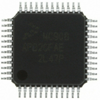
MC908AP32CFAE Freescale Semiconductor, MC908AP32CFAE Datasheet - Page 95

MC908AP32CFAE
Manufacturer Part Number
MC908AP32CFAE
Description
IC MCU 32K FLASH 8MHZ 48-LQFP
Manufacturer
Freescale Semiconductor
Series
HC08r
Specifications of MC908AP32CFAE
Core Processor
HC08
Core Size
8-Bit
Speed
8MHz
Connectivity
I²C, IRSCI, SCI, SPI
Peripherals
LED, LVD, POR, PWM
Number Of I /o
32
Program Memory Size
32KB (32K x 8)
Program Memory Type
FLASH
Ram Size
2K x 8
Voltage - Supply (vcc/vdd)
2.7 V ~ 5.5 V
Data Converters
A/D 8x10b
Oscillator Type
Internal
Operating Temperature
-40°C ~ 85°C
Package / Case
48-LQFP
Controller Family/series
HC08
No. Of I/o's
32
Ram Memory Size
2KB
Cpu Speed
8MHz
No. Of Timers
2
Embedded Interface Type
I2C, SCI, SPI
Rohs Compliant
Yes
Lead Free Status / RoHS Status
Lead free / RoHS Compliant
Eeprom Size
-
Available stocks
Company
Part Number
Manufacturer
Quantity
Price
Company:
Part Number:
MC908AP32CFAE
Manufacturer:
Freescale Semiconductor
Quantity:
10 000
Company:
Part Number:
MC908AP32CFAER
Manufacturer:
Freescale Semiconductor
Quantity:
10 000
- Current page: 95 of 324
- Download datasheet (4Mb)
Acquisition/Lock Time Specifications
6.8 Acquisition/Lock Time Specifications
The acquisition and lock times of the PLL are, in many applications, the most critical PLL design
parameters. Proper design and use of the PLL ensures the highest stability and lowest acquisition/lock
times.
6.8.1 Acquisition/Lock Time Definitions
Typical control systems refer to the acquisition time or lock time as the reaction time, within specified
tolerances, of the system to a step input. In a PLL, the step input occurs when the PLL is turned on or
when it suffers a noise hit. The tolerance is usually specified as a percent of the step input or when the
output settles to the desired value plus or minus a percent of the frequency change. Therefore, the
reaction time is constant in this definition, regardless of the size of the step input. For example, consider
a system with a 5 percent acquisition time tolerance. If a command instructs the system to change from
0Hz to 1MHz, the acquisition time is the time taken for the frequency to reach 1MHz ±50kHz. 50kHz =
5% of the 1MHz step input. If the system is operating at 1MHz and suffers a –100kHz noise hit, the
acquisition time is the time taken to return from 900kHz to 1MHz ±5kHz. 5kHz = 5% of the 100kHz step
input.
Other systems refer to acquisition and lock times as the time the system takes to reduce the error
between the actual output and the desired output to within specified tolerances. Therefore, the acquisition
or lock time varies according to the original error in the output. Minor errors may not even be registered.
Typical PLL applications prefer to use this definition because the system requires the output frequency to
be within a certain tolerance of the desired frequency regardless of the size of the initial error.
6.8.2 Parametric Influences on Reaction Time
Acquisition and lock times are designed to be as short as possible while still providing the highest possible
stability. These reaction times are not constant, however. Many factors directly and indirectly affect the
acquisition time.
The most critical parameter which affects the reaction times of the PLL is the reference frequency, f
.
RDV
This frequency is the input to the phase detector and controls how often the PLL makes corrections. For
stability, the corrections must be small compared to the desired frequency, so several corrections are
required to reduce the frequency error. Therefore, the slower the reference the longer it takes to make
these corrections. This parameter is under user control via the choice of crystal frequency f
and the
XCLK
R value programmed in the reference divider. (See
6.3.3 PLL
Circuits,
6.3.6 Programming the
PLL, and
6.5.5 PLL Reference Divider Select
Register.)
Another critical parameter is the external filter network. The PLL modifies the voltage on the VCO by
adding or subtracting charge from capacitors in this network. Therefore, the rate at which the voltage
changes for a given frequency error (thus change in charge) is proportional to the capacitance. The size
of the capacitor also is related to the stability of the PLL. If the capacitor is too small, the PLL cannot make
small enough adjustments to the voltage and the system cannot lock. If the capacitor is too large, the PLL
may not be able to adjust the voltage in a reasonable time. (See
6.8.3 Choosing a
Filter.)
Also important is the operating voltage potential applied to V
. The power supply potential alters the
DDA
characteristics of the PLL. A fixed value is best. Variable supplies, such as batteries, are acceptable if
they vary within a known range at very slow speeds. Noise on the power supply is not acceptable,
because it causes small frequency errors which continually change the acquisition time of the PLL.
MC68HC908AP Family Data Sheet, Rev. 4
Freescale Semiconductor
95
Related parts for MC908AP32CFAE
Image
Part Number
Description
Manufacturer
Datasheet
Request
R
Part Number:
Description:
Manufacturer:
Freescale Semiconductor, Inc
Datasheet:
Part Number:
Description:
Manufacturer:
Freescale Semiconductor, Inc
Datasheet:
Part Number:
Description:
Manufacturer:
Freescale Semiconductor, Inc
Datasheet:
Part Number:
Description:
Manufacturer:
Freescale Semiconductor, Inc
Datasheet:
Part Number:
Description:
Manufacturer:
Freescale Semiconductor, Inc
Datasheet:
Part Number:
Description:
Manufacturer:
Freescale Semiconductor, Inc
Datasheet:
Part Number:
Description:
Manufacturer:
Freescale Semiconductor, Inc
Datasheet:
Part Number:
Description:
Manufacturer:
Freescale Semiconductor, Inc
Datasheet:
Part Number:
Description:
Manufacturer:
Freescale Semiconductor, Inc
Datasheet:
Part Number:
Description:
Manufacturer:
Freescale Semiconductor, Inc
Datasheet:
Part Number:
Description:
Manufacturer:
Freescale Semiconductor, Inc
Datasheet:
Part Number:
Description:
Manufacturer:
Freescale Semiconductor, Inc
Datasheet:
Part Number:
Description:
Manufacturer:
Freescale Semiconductor, Inc
Datasheet:
Part Number:
Description:
Manufacturer:
Freescale Semiconductor, Inc
Datasheet:
Part Number:
Description:
Manufacturer:
Freescale Semiconductor, Inc
Datasheet:


