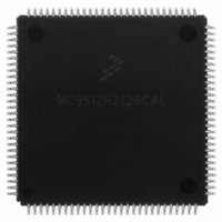
MC9S12HZ128CAL Freescale Semiconductor, MC9S12HZ128CAL Datasheet - Page 298

MC9S12HZ128CAL
Manufacturer Part Number
MC9S12HZ128CAL
Description
IC MCU 16BIT 128K FLASH 112-LQFP
Manufacturer
Freescale Semiconductor
Series
HCS12r
Datasheet
1.MC9S12HZ128CAL.pdf
(692 pages)
Specifications of MC9S12HZ128CAL
Core Processor
HCS12
Core Size
16-Bit
Speed
25MHz
Connectivity
CAN, EBI/EMI, I²C, SCI, SPI
Peripherals
LCD, Motor control PWM, POR, PWM, WDT
Number Of I /o
85
Program Memory Size
128KB (128K x 8)
Program Memory Type
FLASH
Eeprom Size
2K x 8
Ram Size
6K x 8
Voltage - Supply (vcc/vdd)
2.35 V ~ 5.5 V
Data Converters
A/D 16x10b
Oscillator Type
Internal
Operating Temperature
-40°C ~ 85°C
Package / Case
112-LQFP
Processor Series
S12H
Core
HCS12
Data Bus Width
16 bit
Data Ram Size
6 KB
Interface Type
I2C, SCI, SPI
Maximum Clock Frequency
50 MHz
Number Of Programmable I/os
85
Number Of Timers
8
Maximum Operating Temperature
+ 85 C
Mounting Style
SMD/SMT
3rd Party Development Tools
EWHCS12
Minimum Operating Temperature
- 40 C
On-chip Adc
10 bit, 16 Channel
Lead Free Status / RoHS Status
Lead free / RoHS Compliant
Available stocks
Company
Part Number
Manufacturer
Quantity
Price
Company:
Part Number:
MC9S12HZ128CAL
Manufacturer:
Freescale Semiconductor
Quantity:
10 000
- Current page: 298 of 692
- Download datasheet (4Mb)
Chapter 10 Stepper Stall Detector (SSDV1)
10.3.2.3
Read: anytime
Write: anytime
298
l
SSDWAI
SDCPU
Reset
MCEN
AOVIE
FLMC
RTZE
Field
Field
3
2
0
7
6
5
W
R
RTZE
Force Load Register into the Modulus Counter Count Register — This bit always reads zero.
0 Write zero to this bit has no effect.
1 Write one into this bit loads the load register into the modulus counter count register.
Modulus Down-Counter Enable
0 Modulus down-counter is disabled. The modulus counter (MDCCNT) is preset to 0xFFFF. This will prevent an
1 Modulus down-counter is enabled.
Accumulator Overflow Interrupt Enable
0 Interrupt disabled.
1 Interrupt enabled. An interrupt will be generated when the accumulator overflow interrupt flag (AOVIF) is set.
Return to Zero Enable — If this bit is set, the coils are controlled by the SSD and are configured into one of the
four full step states as shown in
0 RTZ is disabled.
1 RTZ is enabled.
Sigma-Delta Converter Power Up — This bit provides on/off control for the sigma-delta converter allowing
reduced MCU power consumption. Because the analog circuit is turned off when powered down, the sigma-delta
converter requires a recovery time after it is powered up.
0 Sigma-delta converter is powered down.
1 Sigma-delta converter is powered up.
SSD Disabled during Wait Mode — When entering Wait Mode, this bit provides on/off control over the SSD
allowing reduced MCU power consumption. Because the analog circuit is turned off when powered down, the
sigma-delta converter requires a recovery time after exit from Wait Mode.
0 SSD continues to run in WAIT mode.
1 Entering WAIT mode freezes the clock to the prescaler divider, powers down the sigma-delta converter, and
Stepper Stall Detector Control Register (SSDCTL)
0
7
early interrupt flag when the modulus down-counter is enabled.
if RTZE bit is set, the sine and cosine coils are recirculated via VSSM.
= Unimplemented or Reserved
Figure 10-4. Stepper Stall Detector Control Register (SSDCTL)
SDCPU
0
6
Table 10-7. MDCCTL Field Descriptions (continued)
Table 10-8. SSDCTL Field Descriptions
SSDWAI
MC9S12HZ256 Data Sheet, Rev. 2.05
0
5
Table
10-6. If this bit is cleared, the coils are not controlled by the SSD.
FTST
0
4
Description
Description
0
0
3
0
0
2
Freescale Semiconductor
0
1
ACLKS
0
0
Related parts for MC9S12HZ128CAL
Image
Part Number
Description
Manufacturer
Datasheet
Request
R
Part Number:
Description:
Manufacturer:
Freescale Semiconductor, Inc
Datasheet:
Part Number:
Description:
Manufacturer:
Freescale Semiconductor, Inc
Datasheet:
Part Number:
Description:
Manufacturer:
Freescale Semiconductor, Inc
Datasheet:
Part Number:
Description:
Manufacturer:
Freescale Semiconductor, Inc
Datasheet:
Part Number:
Description:
Manufacturer:
Freescale Semiconductor, Inc
Datasheet:
Part Number:
Description:
Manufacturer:
Freescale Semiconductor, Inc
Datasheet:
Part Number:
Description:
Manufacturer:
Freescale Semiconductor, Inc
Datasheet:
Part Number:
Description:
Manufacturer:
Freescale Semiconductor, Inc
Datasheet:
Part Number:
Description:
Manufacturer:
Freescale Semiconductor, Inc
Datasheet:
Part Number:
Description:
Manufacturer:
Freescale Semiconductor, Inc
Datasheet:
Part Number:
Description:
Manufacturer:
Freescale Semiconductor, Inc
Datasheet:
Part Number:
Description:
Manufacturer:
Freescale Semiconductor, Inc
Datasheet:
Part Number:
Description:
Manufacturer:
Freescale Semiconductor, Inc
Datasheet:
Part Number:
Description:
Manufacturer:
Freescale Semiconductor, Inc
Datasheet:
Part Number:
Description:
Manufacturer:
Freescale Semiconductor, Inc
Datasheet:


