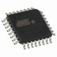
ATMEGA16M1-AU Atmel, ATMEGA16M1-AU Datasheet - Page 138

ATMEGA16M1-AU
Manufacturer Part Number
ATMEGA16M1-AU
Description
IC MCU AVR 16K FLASH 32TQFP
Manufacturer
Atmel
Series
AVR® ATmegar
Specifications of ATMEGA16M1-AU
Core Processor
AVR
Core Size
8-Bit
Speed
16MHz
Connectivity
CAN, LIN, SPI, UART/USART
Peripherals
Brown-out Detect/Reset, POR, PWM, Temp Sensor, WDT
Program Memory Size
16KB (8K x 16)
Program Memory Type
FLASH
Eeprom Size
512 x 8
Ram Size
1K x 8
Voltage - Supply (vcc/vdd)
2.7 V ~ 5.5 V
Data Converters
A/D 11x10b; D/A 1x10b
Oscillator Type
Internal
Operating Temperature
-40°C ~ 85°C
Package / Case
32-TQFP, 32-VQFP
Lead Free Status / RoHS Status
Lead free / RoHS Compliant
Number Of I /o
-
Available stocks
Company
Part Number
Manufacturer
Quantity
Price
- Current page: 138 of 341
- Download datasheet (6Mb)
17.5.3.2
138
ATmega16M1/32M1/64M1
Center Aligned Mode
In center aligned mode, the center of PSCOUTnA and PSCOUTnB signals are centered.
Figure 17-6. PSCOUTnA & PSCOUTnB Basic Waveforms in Center Aligned Mode
On-Time 0 = 2 × POCRnSAH/L × 1/Fclkpsc
On-Time 1 = 2 × (POCRnRBH/L - POCRnSBH/L + 1) × 1/Fclkpsc
Dead-Time = (POCRnSBH/L - POCRnSAH/L) × 1/Fclkpsc
PSC Cycle = 2 × (POCRnRBH/L + 1) × 1/Fclkpsc
Note:
Note that in center aligned mode, POCRnRAH/L is not required (as it is in one-ramp mode) to
control PSC Output waveform timing. This allows POCRnRAH/L to be freely used to adjust ADC
synchronization.
POCRnRB
POCRnSB
POCRnSA
PSCOUTnA
PSCOUTnB
Minimal value for PSC Cycle = 2 × 1/Fclkpsc
On-Time 1
See “Analog Synchronization” on page 145.
PSC Counter
Dead-Time
On-Time 0
PSC Cycle
0
Dead-Time
On-Time 1
8209D–AVR–11/10
Related parts for ATMEGA16M1-AU
Image
Part Number
Description
Manufacturer
Datasheet
Request
R

Part Number:
Description:
Manufacturer:
Atmel Corporation
Datasheet:

Part Number:
Description:
IC AVR MCU 16K 16MHZ 5V 44TQFP
Manufacturer:
Atmel
Datasheet:

Part Number:
Description:
IC AVR MCU 16K 16MHZ 5V 44-QFN
Manufacturer:
Atmel
Datasheet:

Part Number:
Description:
IC AVR MCU 16K 16MHZ 5V 40DIP
Manufacturer:
Atmel
Datasheet:

Part Number:
Description:
MCU AVR 16K FLASH 16MHZ 44-QFN
Manufacturer:
Atmel
Datasheet:

Part Number:
Description:
IC AVR MCU 16K 16MHZ COM 40-DIP
Manufacturer:
Atmel
Datasheet:

Part Number:
Description:
IC AVR MCU 16K 16MHZ COM 44-QFN
Manufacturer:
Atmel
Datasheet:

Part Number:
Description:
IC AVR MCU 16K 16MHZ IND 40-DIP
Manufacturer:
Atmel
Datasheet:

Part Number:
Description:
IC AVR MCU 16K 16MHZ IND 44-QFN
Manufacturer:
Atmel
Datasheet:

Part Number:
Description:
IC AVR MCU 16K 16MHZ IND 44-TQFP
Manufacturer:
Atmel
Datasheet:

Part Number:
Description:
IC MCU 8BIT 16KB FLASH 44TQFP
Manufacturer:
Atmel
Datasheet:

Part Number:
Description:
MCU AVR 16K FLASH 16MHZ 44-TQFP
Manufacturer:
Atmel
Datasheet:

Part Number:
Description:
IC AVR MCU 16K 16MHZ COM 44-TQFP
Manufacturer:
Atmel
Datasheet:


