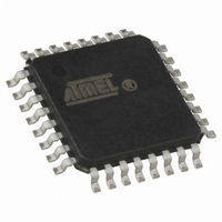
ATMEGA16M1-AU Atmel, ATMEGA16M1-AU Datasheet - Page 150

ATMEGA16M1-AU
Manufacturer Part Number
ATMEGA16M1-AU
Description
IC MCU AVR 16K FLASH 32TQFP
Manufacturer
Atmel
Series
AVR® ATmegar
Specifications of ATMEGA16M1-AU
Core Processor
AVR
Core Size
8-Bit
Speed
16MHz
Connectivity
CAN, LIN, SPI, UART/USART
Peripherals
Brown-out Detect/Reset, POR, PWM, Temp Sensor, WDT
Program Memory Size
16KB (8K x 16)
Program Memory Type
FLASH
Eeprom Size
512 x 8
Ram Size
1K x 8
Voltage - Supply (vcc/vdd)
2.7 V ~ 5.5 V
Data Converters
A/D 11x10b; D/A 1x10b
Oscillator Type
Internal
Operating Temperature
-40°C ~ 85°C
Package / Case
32-TQFP, 32-VQFP
Lead Free Status / RoHS Status
Lead free / RoHS Compliant
Number Of I /o
-
Available stocks
Company
Part Number
Manufacturer
Quantity
Price
- Current page: 150 of 341
- Download datasheet (6Mb)
17.16.8
17.16.9
150
ATmega16M1/32M1/64M1
PCTL – PSC Control Register
PMICn – PSC Module n Input Control Register
• Bit 1:0 – Res: Reserved
These bits are reserved and will always read as zero.
• Bit 7:6 – PPRE1:0: PSC Prescaler Select
This two bits select the PSC input clock division factor. All generated waveform will be modified
by this factor.
Table 17-11. PSC Prescaler Selection
• Bit 5 – PCLKSEL: PSC Input Clock Select
This bit is used to select between CLK
Set this bit to select the fast clock input (CLK
Clear this bit to select the slow clock input (CLK
• Bit 4:2 – Res: Reserved
These bits are reserved and will always read as zero.
• Bit 1 – PCCYC: PSC Complete Cycle
When this bit is set, the PSC completes the entire waveform cycle before halt operation
requested by clearing PRUN.
• Bit 0 – PRUN: PSC Run
Writing this bit to one starts the PSC.
The Input Control Registers are used to configure the 2 PSC’s Retrigger/Fault block A & B. The
2 blocks are identical, so they are configured on the same way.
• Bit 7 – POVENn: PSC Module n Overlap Enable
Set this bit to disactivate the Overlap Protection. See
Bit
Read/Write
Initial Value
Bit
Read/Write
Initial Value
PPRE1
0
0
1
1
POVENn
PPRE0
0
1
0
1
PPRE1
R/W
R/W
7
0
7
0
PISELn
PPRE0
R/W
R/W
6
0
6
0
Description
No divider on PSC input clock
Divide the PSC input clock by 4
Divide the PSC input clock by 32
Divide the PSC clock by 256
PCLKSEL
PELEVn
R/W
R/W
5
0
5
0
PLL
or CLK
PFLTEn
R/W
R
4
0
4
0
-
PLL
).
IO
IO
).
clocks.
PAOCn
R/W
R
3
0
3
0
“Overlap Protection” on page
-
PRFMn2
R/W
R
2
0
2
0
-
PRFMn1
PCCYC
R/W
R/W
1
0
1
0
PRFMn0
PRUN
R/W
R/W
0
0
0
0
8209D–AVR–11/10
140.
PMICn
PCTL
Related parts for ATMEGA16M1-AU
Image
Part Number
Description
Manufacturer
Datasheet
Request
R

Part Number:
Description:
Manufacturer:
Atmel Corporation
Datasheet:

Part Number:
Description:
IC AVR MCU 16K 16MHZ 5V 44TQFP
Manufacturer:
Atmel
Datasheet:

Part Number:
Description:
IC AVR MCU 16K 16MHZ 5V 44-QFN
Manufacturer:
Atmel
Datasheet:

Part Number:
Description:
IC AVR MCU 16K 16MHZ 5V 40DIP
Manufacturer:
Atmel
Datasheet:

Part Number:
Description:
MCU AVR 16K FLASH 16MHZ 44-QFN
Manufacturer:
Atmel
Datasheet:

Part Number:
Description:
IC AVR MCU 16K 16MHZ COM 40-DIP
Manufacturer:
Atmel
Datasheet:

Part Number:
Description:
IC AVR MCU 16K 16MHZ COM 44-QFN
Manufacturer:
Atmel
Datasheet:

Part Number:
Description:
IC AVR MCU 16K 16MHZ IND 40-DIP
Manufacturer:
Atmel
Datasheet:

Part Number:
Description:
IC AVR MCU 16K 16MHZ IND 44-QFN
Manufacturer:
Atmel
Datasheet:

Part Number:
Description:
IC AVR MCU 16K 16MHZ IND 44-TQFP
Manufacturer:
Atmel
Datasheet:

Part Number:
Description:
IC MCU 8BIT 16KB FLASH 44TQFP
Manufacturer:
Atmel
Datasheet:

Part Number:
Description:
MCU AVR 16K FLASH 16MHZ 44-TQFP
Manufacturer:
Atmel
Datasheet:

Part Number:
Description:
IC AVR MCU 16K 16MHZ COM 44-TQFP
Manufacturer:
Atmel
Datasheet:


