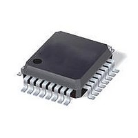
ST7FLITE49K2T6 STMicroelectronics, ST7FLITE49K2T6 Datasheet - Page 56

ST7FLITE49K2T6
Manufacturer Part Number
ST7FLITE49K2T6
Description
IC MCU 8BIT 8K FLASH 32LQFP
Manufacturer
STMicroelectronics
Series
ST7r
Datasheet
1.ST7FLITE49K2T6TR.pdf
(245 pages)
Specifications of ST7FLITE49K2T6
Core Processor
ST7
Core Size
8-Bit
Speed
8MHz
Connectivity
I²C, SPI
Peripherals
LVD, POR, PWM, WDT
Number Of I /o
24
Program Memory Size
8KB (8K x 8)
Program Memory Type
FLASH
Eeprom Size
256 x 8
Ram Size
384 x 8
Voltage - Supply (vcc/vdd)
2.4 V ~ 5.5 V
Data Converters
A/D 10x10b
Oscillator Type
Internal
Operating Temperature
-40°C ~ 85°C
Package / Case
32-LQFP
Processor Series
ST7FLITE4x
Core
ST7
Data Bus Width
8 bit
Data Ram Size
384 B
Interface Type
I2C, SPI
Maximum Clock Frequency
8 MHz
Number Of Programmable I/os
24
Number Of Timers
4
Maximum Operating Temperature
+ 85 C
Mounting Style
SMD/SMT
Development Tools By Supplier
ST7FLITE-SK/RAIS, ST7FLI49M-D/RAIS, STX-RLINK
Minimum Operating Temperature
- 40 C
On-chip Adc
10 bit, 10 Channel
For Use With
497-8399 - BOARD EVAL ST7LITE49M/STLED316S497-5858 - EVAL BOARD PLAYBACK ST7FLITE
Lead Free Status / RoHS Status
Lead free / RoHS Compliant
Available stocks
Company
Part Number
Manufacturer
Quantity
Price
Company:
Part Number:
ST7FLITE49K2T6
Manufacturer:
ST
Quantity:
3 000
Company:
Part Number:
ST7FLITE49K2T6
Manufacturer:
STMicroelectronics
Quantity:
10 000
Company:
Part Number:
ST7FLITE49K2T6TR
Manufacturer:
STMicroelectronics
Quantity:
10 000
Interrupts
8.2.1
Note:
8.2.2
56/245
1
2
Servicing pending interrupts
As several interrupts can be pending at the same time, the interrupt to be taken into account
is determined by the following two-step process:
●
●
Figure 21
Figure 21. Priority decision process
When an interrupt request is not serviced immediately, it is latched and then processed
when its software priority combined with the hardware priority becomes the highest one.
The hardware priority is exclusive while the software one is not. This allows the previous
process to succeed with only one interrupt.
RESET and TRAP can be considered as having the highest software priority in the decision
process.
Interrupt vector sources
Two interrupt source types are managed by the ST7 interrupt controller: the non-maskable
type (RESET, TRAP) and the maskable type (external or from internal peripherals).
Non-maskable sources
These sources are processed regardless of the state of the I1 and I0 bits of the CC register
(see
corresponding vector is loaded in the PC register and the I1 and I0 bits of the CC are set to
disable interrupts (level 3). These sources allow the processor to exit Halt mode.
●
●
The highest software priority interrupt is serviced,
If several interrupts have the same software priority then the interrupt with the highest
hardware priority is serviced first.
TRAP (non maskable software interrupt)
This software interrupt is serviced when the TRAP instruction is executed. It will be
serviced according to the flowchart in
RESET
The RESET source has the highest priority in the ST7. This means that the first current
routine has the highest software priority (level 3) and the highest hardware priority.
See the RESET chapter for more details.
Figure
describes this decision process.
20). After stacking the PC, X, A and CC registers (except for RESET), the
PRIORITY SERVICED
HIGHEST HARDWARE
Same
INTERRUPTS
SOFTWARE
PRIORITY
PENDING
Figure
HIGHEST SOFTWARE
PRIORITY SERVICED
20.
Different
ST7LITE49K2


