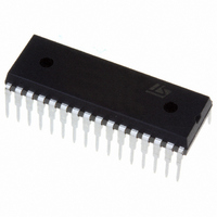
ST72F264G2B6 STMicroelectronics, ST72F264G2B6 Datasheet - Page 127

ST72F264G2B6
Manufacturer Part Number
ST72F264G2B6
Description
MCU 8-BIT 8K FLASH 32-SDIP
Manufacturer
STMicroelectronics
Series
ST7r
Specifications of ST72F264G2B6
Mfg Application Notes
ST7 Checksum Capability, AN1070 App Note
Core Processor
ST7
Core Size
8-Bit
Speed
16MHz
Connectivity
I²C, SCI, SPI
Peripherals
LVD, POR, PWM, WDT
Number Of I /o
22
Program Memory Size
8KB (8K x 8)
Program Memory Type
FLASH
Ram Size
256 x 8
Voltage - Supply (vcc/vdd)
2.7 V ~ 5.5 V
Data Converters
A/D 6x10b
Oscillator Type
Internal
Operating Temperature
-40°C ~ 85°C
Package / Case
32-SDIP (0.400", 10.16mm)
Processor Series
ST72F2x
Core
ST7
Data Bus Width
8 bit
Data Ram Size
256 B
Interface Type
I2C, SCI, SPI
Maximum Clock Frequency
8 MHz
Number Of Programmable I/os
22
Number Of Timers
3
Maximum Operating Temperature
+ 85 C
Mounting Style
Through Hole
Development Tools By Supplier
ST7F264-IND/USB, ST72F34X-SK/RAIS, ST7MDT10-DVP3, ST7MDT10-EMU3, STX-RLINK
Minimum Operating Temperature
- 40 C
On-chip Adc
10 bit, 6 Channel
For Use With
497-6423 - BOARD EVAL BASED ON ST72264G1497-5046 - KIT TOOL FOR ST7/UPSD/STR7 MCU
Lead Free Status / RoHS Status
Lead free / RoHS Compliant
Eeprom Size
-
Lead Free Status / Rohs Status
Details
Other names
497-5570
Available stocks
Company
Part Number
Manufacturer
Quantity
Price
Company:
Part Number:
ST72F264G2B6
Manufacturer:
ST
Quantity:
10
Company:
Part Number:
ST72F264G2B6
Manufacturer:
NEC
Quantity:
6 097
Part Number:
ST72F264G2B6
Manufacturer:
ST
Quantity:
20 000
- Current page: 127 of 235
- Download datasheet (2Mb)
Table 80. TIMERx_ICAP_Mode
Function Name
Function Prototype
Behaviour Description
Input Parameter 1
Input Parameter 2
Output Parameter
Required Preconditions
Functions called
Postconditions
See also
1) Function not available in ST72F65.
TIMERx_ICAP_Mode
Void TIMERx_ICAP_Mode(Timer_Icap ICAP_I,
Timer_Edge EDGE_SELECT_Y)
Configures the timer to Input capture mode. It determines
the type of level transition on input capture pins.This func-
tion should be called twice in order to use both ICAP1 &
ICAP2.
TIMER_ICAP_I
where I can be 1 or 2.
I = 1, Input capture 1 is selected.
I = 2, Input capture 2 is selected.
TIMER_EDGE_Y
where Y can be 0 or 1.
Y= 0, Capture occurs at falling edge.
Y= 1, Capture occurs at the rising edge.
None
1. Input Capture pin used must be configured as floating
input.
2. Only input capture 2 can be used if PWM or OPM is ac-
tive.
None
1. Timer configured for input capture mode.
2. To detect the occurrence of valid edge, you can poll the
input capture flag using the function
TIMERx_Status_Flag. This is in case you have not ena-
bled the input capture interrupt.
TIMERx_Status_Flag,TIMERx_PWM_Mode,
TIMERx_OPM_Mode, TIMERx_ICAP_Getvalue
1)
Function Descriptions
127/235
Related parts for ST72F264G2B6
Image
Part Number
Description
Manufacturer
Datasheet
Request
R

Part Number:
Description:
STMicroelectronics [RIPPLE-CARRY BINARY COUNTER/DIVIDERS]
Manufacturer:
STMicroelectronics
Datasheet:

Part Number:
Description:
STMicroelectronics [LIQUID-CRYSTAL DISPLAY DRIVERS]
Manufacturer:
STMicroelectronics
Datasheet:

Part Number:
Description:
BOARD EVAL FOR MEMS SENSORS
Manufacturer:
STMicroelectronics
Datasheet:

Part Number:
Description:
NPN TRANSISTOR POWER MODULE
Manufacturer:
STMicroelectronics
Datasheet:

Part Number:
Description:
TURBOSWITCH ULTRA-FAST HIGH VOLTAGE DIODE
Manufacturer:
STMicroelectronics
Datasheet:

Part Number:
Description:
Manufacturer:
STMicroelectronics
Datasheet:

Part Number:
Description:
DIODE / SCR MODULE
Manufacturer:
STMicroelectronics
Datasheet:

Part Number:
Description:
DIODE / SCR MODULE
Manufacturer:
STMicroelectronics
Datasheet:

Part Number:
Description:
Search -----> STE16N100
Manufacturer:
STMicroelectronics
Datasheet:

Part Number:
Description:
Search ---> STE53NA50
Manufacturer:
STMicroelectronics
Datasheet:

Part Number:
Description:
NPN Transistor Power Module
Manufacturer:
STMicroelectronics
Datasheet:

Part Number:
Description:
DIODE / SCR MODULE
Manufacturer:
STMicroelectronics
Datasheet:


