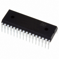
ST72F264G2B6 STMicroelectronics, ST72F264G2B6 Datasheet - Page 148

ST72F264G2B6
Manufacturer Part Number
ST72F264G2B6
Description
MCU 8-BIT 8K FLASH 32-SDIP
Manufacturer
STMicroelectronics
Series
ST7r
Specifications of ST72F264G2B6
Mfg Application Notes
ST7 Checksum Capability, AN1070 App Note
Core Processor
ST7
Core Size
8-Bit
Speed
16MHz
Connectivity
I²C, SCI, SPI
Peripherals
LVD, POR, PWM, WDT
Number Of I /o
22
Program Memory Size
8KB (8K x 8)
Program Memory Type
FLASH
Ram Size
256 x 8
Voltage - Supply (vcc/vdd)
2.7 V ~ 5.5 V
Data Converters
A/D 6x10b
Oscillator Type
Internal
Operating Temperature
-40°C ~ 85°C
Package / Case
32-SDIP (0.400", 10.16mm)
Processor Series
ST72F2x
Core
ST7
Data Bus Width
8 bit
Data Ram Size
256 B
Interface Type
I2C, SCI, SPI
Maximum Clock Frequency
8 MHz
Number Of Programmable I/os
22
Number Of Timers
3
Maximum Operating Temperature
+ 85 C
Mounting Style
Through Hole
Development Tools By Supplier
ST7F264-IND/USB, ST72F34X-SK/RAIS, ST7MDT10-DVP3, ST7MDT10-EMU3, STX-RLINK
Minimum Operating Temperature
- 40 C
On-chip Adc
10 bit, 6 Channel
For Use With
497-6423 - BOARD EVAL BASED ON ST72264G1497-5046 - KIT TOOL FOR ST7/UPSD/STR7 MCU
Lead Free Status / RoHS Status
Lead free / RoHS Compliant
Eeprom Size
-
Lead Free Status / Rohs Status
Details
Other names
497-5570
Available stocks
Company
Part Number
Manufacturer
Quantity
Price
Company:
Part Number:
ST72F264G2B6
Manufacturer:
ST
Quantity:
10
Company:
Part Number:
ST72F264G2B6
Manufacturer:
NEC
Quantity:
6 097
Part Number:
ST72F264G2B6
Manufacturer:
ST
Quantity:
20 000
- Current page: 148 of 235
- Download datasheet (2Mb)
Function Descriptions
EXAMPLE:
The following C program shows the use of the TIMER8 functions.
Program description:
It compares the output compare2 register value with the free running counter, checks the oc-
currence of (event) leading edge at ICAP2 pin. It generates PWM signal with 10KHz frequency
and with 33% Duty cycle at the OCMP1 pin if _Enable_PWM_ is defined in main.c or it gen-
erates the 0.1ms pulse at OCMP1 pin, if _Enable_OPM_ is defined in main.c (Fcpu = 8 MHz).
/* Program start */
#include "st7lib_config.h"
//prototype declaration
void main(void);
void TIMER8_IT_Routine(void);
void main(void)
{
}
/* Program end */
148/235
unsigned char TIMER8_OCR_VALUE = 0x50;
/* Configuring the Port B pin 0 & 2 as floating for ICAP1 and ICAP2 */
IO_Input(IO_FLOATING,IO_PORT_B,((unsigned char)IO_PIN_0 | (unsigned char)
TIMER8_Init (TIMER8_FCPU_8);
EnableInterrupts
/*
TIMER8_OCMP_Mode(TIMER8_OCMP_2,TIMER8_OCR_VALUE,TIMER8_OUTPUT_R );
while(!(TIMER8_Status_Flag(TIMER8_FLAG_OCF2)== TRUE));
TIMER8_Clear_Flag(TIMER8_FLAG_OCF2);
TIMER8_IT_Enable(TIMER8_ICAP_IT_ENABLE);
/*Detect rising edge at ICAP2 pin*/
TIMER8_ICAP_Mode(TIMER8_ICAP_2,TIMER8_EDGE_1);
/*
#ifdef _Enable_PWM_
#endif
/*
#ifdef _Enable_OPM_
#endif
while(1);
Timer8 compares 0x50 with free running counter
Run TIMER8 in PWM mode if _Enable_PWM_ is defined
Run TIMER8 in OPM mode if _Enable_OPM_ is defined
TIMER8_PWM_Mode(TIMER8_OUTPUT1_F,TIMER8_OUTPUT2_R,0x1C,0x5F);
TIMER8_Clear_Flag(TIMER8_FLAG_ICF1);
TIMER8_Mode_Disable(TIMER8_MODE_5);
/* 0.1ms pulse */
TIMER8_OPM_Mode(TIMER8_EDGE_1,TIMER8_OUTPUT1_F,TIMER8_OUTPUT2_R,0x5F);
/* File for user to select the required device */
/* Timer8 Clock to Fcpu/8 and reset counter */
/* Generate PWM of frequency of 10 KHz */
/* Clear output compare2 flag */
/* Clear Input capture1 Flag */
/* Enable capture interrupt */
IO_PIN_2));
/* Clear I bit in CC reg */
*/
*/
*/
/* For testing only */
/* Disable PWM */
Related parts for ST72F264G2B6
Image
Part Number
Description
Manufacturer
Datasheet
Request
R

Part Number:
Description:
STMicroelectronics [RIPPLE-CARRY BINARY COUNTER/DIVIDERS]
Manufacturer:
STMicroelectronics
Datasheet:

Part Number:
Description:
STMicroelectronics [LIQUID-CRYSTAL DISPLAY DRIVERS]
Manufacturer:
STMicroelectronics
Datasheet:

Part Number:
Description:
BOARD EVAL FOR MEMS SENSORS
Manufacturer:
STMicroelectronics
Datasheet:

Part Number:
Description:
NPN TRANSISTOR POWER MODULE
Manufacturer:
STMicroelectronics
Datasheet:

Part Number:
Description:
TURBOSWITCH ULTRA-FAST HIGH VOLTAGE DIODE
Manufacturer:
STMicroelectronics
Datasheet:

Part Number:
Description:
Manufacturer:
STMicroelectronics
Datasheet:

Part Number:
Description:
DIODE / SCR MODULE
Manufacturer:
STMicroelectronics
Datasheet:

Part Number:
Description:
DIODE / SCR MODULE
Manufacturer:
STMicroelectronics
Datasheet:

Part Number:
Description:
Search -----> STE16N100
Manufacturer:
STMicroelectronics
Datasheet:

Part Number:
Description:
Search ---> STE53NA50
Manufacturer:
STMicroelectronics
Datasheet:

Part Number:
Description:
NPN Transistor Power Module
Manufacturer:
STMicroelectronics
Datasheet:

Part Number:
Description:
DIODE / SCR MODULE
Manufacturer:
STMicroelectronics
Datasheet:


