ST72F264G2B6 STMicroelectronics, ST72F264G2B6 Datasheet - Page 141
ST72F264G2B6
Manufacturer Part Number
ST72F264G2B6
Description
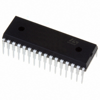
MCU 8-BIT 8K FLASH 32-SDIP
Manufacturer
STMicroelectronics
Series
ST7r
Specifications of ST72F264G2B6
Mfg Application Notes
ST7 Checksum Capability, AN1070 App Note
Core Processor
ST7
Core Size
8-Bit
Speed
16MHz
Connectivity
I²C, SCI, SPI
Peripherals
LVD, POR, PWM, WDT
Number Of I /o
22
Program Memory Size
8KB (8K x 8)
Program Memory Type
FLASH
Ram Size
256 x 8
Voltage - Supply (vcc/vdd)
2.7 V ~ 5.5 V
Data Converters
A/D 6x10b
Oscillator Type
Internal
Operating Temperature
-40°C ~ 85°C
Package / Case
32-SDIP (0.400", 10.16mm)
Processor Series
ST72F2x
Core
ST7
Data Bus Width
8 bit
Data Ram Size
256 B
Interface Type
I2C, SCI, SPI
Maximum Clock Frequency
8 MHz
Number Of Programmable I/os
22
Number Of Timers
3
Maximum Operating Temperature
+ 85 C
Mounting Style
Through Hole
Development Tools By Supplier
ST7F264-IND/USB, ST72F34X-SK/RAIS, ST7MDT10-DVP3, ST7MDT10-EMU3, STX-RLINK
Minimum Operating Temperature
- 40 C
On-chip Adc
10 bit, 6 Channel
For Use With
497-6423 - BOARD EVAL BASED ON ST72264G1497-5046 - KIT TOOL FOR ST7/UPSD/STR7 MCU
Lead Free Status / RoHS Status
Lead free / RoHS Compliant
Eeprom Size
-
Lead Free Status / Rohs Status
Details
Other names
497-5570
Available stocks
Company
Part Number
Manufacturer
Quantity
Price
Company:

Part Number:
ST72F264G2B6
Manufacturer:
ST
Quantity:
10
Company:
Part Number:
ST72F264G2B6
Manufacturer:
NEC
Quantity:
6 097
Part Number:
ST72F264G2B6
Manufacturer:
ST
Quantity:
20 000


Table 91. TIMER8_PWM_Mode
Notes:
– Flags for compare1 & compare2 can not be set by hardware in PWM mode, therefore the
Function Name
Function Prototype
Behaviour Description
Input Parameter 1
Input Parameter 2
Input Parameter 3
Input Parameter 4
Output Parameters
Required Preconditions
Functions called
Postconditions
See also
output compare interrupt is inhibited.
TIMER8_PWM_Mode
Void TIMER8_PWM_Mode(Timer8_Olevel
OUTPUT1_L,Timer8_Olevel OUTPUT2_L,unsigned char
OCR1_VALUE,unsigned char OCR2_VALUE)
Configures the timer8 in Pulse width modulation mode. It
enables the generation of a signal with frequency and duty
cycle depending upon the input parameters you have giv-
en. If PWM and OPM modes are both active then only
PWM works. In PWM mode, the ICAP1 pin cannot be used
for input capture function, but ICAP2 can be used.
TIMER8_OUTPUT1_F
Low level is reflected at the output compare1 pin after suc-
cessful comparison of output compare1 register with free
running counter.
TIMER8_OUTPUT1_R
High level is reflected at the output compare1 pin after
successful comparison of output compare1 register with
free running counter.
TIMER8_OUTPUT2_F
Low level is reflected at the output compare1 pin after suc-
cessful comparison of output compare2 register with free
running counter.
TIMER8_OUTPUT2_R
High level is reflected at the output compare1 pin after
successful comparison of output compare2 register with
free running counter.
OC1R_VALUE
You can select this value from 0x00 to 0xFC.
OC2R_VALUE
You can select this value from 0x00 to 0xFC.
None
1.Timer8 correctly configured.
2.Timer8 interrupt due to input capture1 can be used by
enabling the input capture interrupt.
None
1.Timer8 is active in Pulse width modulation mode and
waveform can be seen on OCMP1 pin.
2. Output compare interrupt is inhibited.
TIMER8_Init,TIMER8_ICAP_Mode
Function Descriptions
141/235
Related parts for ST72F264G2B6
Image
Part Number
Description
Manufacturer
Datasheet
Request
R

Part Number:
Description:
STMicroelectronics [RIPPLE-CARRY BINARY COUNTER/DIVIDERS]
Manufacturer:
STMicroelectronics
Datasheet:
Part Number:
Description:
STMicroelectronics [LIQUID-CRYSTAL DISPLAY DRIVERS]
Manufacturer:
STMicroelectronics
Datasheet:

Part Number:
Description:
BOARD EVAL FOR MEMS SENSORS
Manufacturer:
STMicroelectronics
Datasheet:
Part Number:
Description:
NPN TRANSISTOR POWER MODULE
Manufacturer:
STMicroelectronics
Datasheet:
Part Number:
Description:
TURBOSWITCH ULTRA-FAST HIGH VOLTAGE DIODE
Manufacturer:
STMicroelectronics
Datasheet:
Part Number:
Description:
Manufacturer:
STMicroelectronics
Datasheet:
Part Number:
Description:
DIODE / SCR MODULE
Manufacturer:
STMicroelectronics
Datasheet:
Part Number:
Description:
DIODE / SCR MODULE
Manufacturer:
STMicroelectronics
Datasheet:
Part Number:
Description:
Search -----> STE16N100
Manufacturer:
STMicroelectronics
Datasheet:
Part Number:
Description:
Search ---> STE53NA50
Manufacturer:
STMicroelectronics
Datasheet:
Part Number:
Description:
NPN Transistor Power Module
Manufacturer:
STMicroelectronics
Datasheet:
Part Number:
Description:
DIODE / SCR MODULE
Manufacturer:
STMicroelectronics
Datasheet: