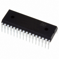
ST72F264G2B6 STMicroelectronics, ST72F264G2B6 Datasheet - Page 51

ST72F264G2B6
Manufacturer Part Number
ST72F264G2B6
Description
MCU 8-BIT 8K FLASH 32-SDIP
Manufacturer
STMicroelectronics
Series
ST7r
Specifications of ST72F264G2B6
Mfg Application Notes
ST7 Checksum Capability, AN1070 App Note
Core Processor
ST7
Core Size
8-Bit
Speed
16MHz
Connectivity
I²C, SCI, SPI
Peripherals
LVD, POR, PWM, WDT
Number Of I /o
22
Program Memory Size
8KB (8K x 8)
Program Memory Type
FLASH
Ram Size
256 x 8
Voltage - Supply (vcc/vdd)
2.7 V ~ 5.5 V
Data Converters
A/D 6x10b
Oscillator Type
Internal
Operating Temperature
-40°C ~ 85°C
Package / Case
32-SDIP (0.400", 10.16mm)
Processor Series
ST72F2x
Core
ST7
Data Bus Width
8 bit
Data Ram Size
256 B
Interface Type
I2C, SCI, SPI
Maximum Clock Frequency
8 MHz
Number Of Programmable I/os
22
Number Of Timers
3
Maximum Operating Temperature
+ 85 C
Mounting Style
Through Hole
Development Tools By Supplier
ST7F264-IND/USB, ST72F34X-SK/RAIS, ST7MDT10-DVP3, ST7MDT10-EMU3, STX-RLINK
Minimum Operating Temperature
- 40 C
On-chip Adc
10 bit, 6 Channel
For Use With
497-6423 - BOARD EVAL BASED ON ST72264G1497-5046 - KIT TOOL FOR ST7/UPSD/STR7 MCU
Lead Free Status / RoHS Status
Lead free / RoHS Compliant
Eeprom Size
-
Lead Free Status / Rohs Status
Details
Other names
497-5570
Available stocks
Company
Part Number
Manufacturer
Quantity
Price
Company:
Part Number:
ST72F264G2B6
Manufacturer:
ST
Quantity:
10
Company:
Part Number:
ST72F264G2B6
Manufacturer:
NEC
Quantity:
6 097
Part Number:
ST72F264G2B6
Manufacturer:
ST
Quantity:
20 000
WATCHDOG TIMER (Cont’d)
11.1.5 Low Power Modes
11.1.6 Hardware Watchdog Option
If Hardware Watchdog is selected by option byte,
the watchdog is always active and the WDGA bit in
the WDGCR is not used. Refer to the Option Byte
description.
11.1.7 Using Halt Mode with the WDG
(WDGHALT option)
The following recommendation applies if Halt
mode is used when the watchdog is enabled.
– Before executing the HALT instruction, refresh
11.1.8 Interrupts
None.
the WDG counter, to avoid an unexpected WDG
reset immediately after waking up the microcon-
troller.
SLOW
Mode
WAIT
HALT
Description
No effect on Watchdog.
No effect on Watchdog.
OIE bit in
MCCSR
register
0
0
1
WDGHALT bit
in Option
Byte
0
1
x
No Watchdog reset is generated. The MCU enters Halt mode. The Watch-
dog counter is decremented once and then stops counting and is no longer
able to generate a watchdog reset until the MCU receives an external inter-
rupt or a reset.
If an external interrupt is received, the Watchdog restarts counting after 256
or 4096 CPU clocks. If a reset is generated, the Watchdog is disabled (reset
state) unless Hardware Watchdog is selected by option byte. For applica-
tion recommendations see
A reset is generated.
No reset is generated. The MCU enters Active Halt mode. The Watchdog
counter is not decremented. It stop counting. When the MCU receives an
oscillator interrupt or external interrupt, the Watchdog restarts counting im-
mediately. When the MCU receives a reset the Watchdog restarts counting
after 256 or 4096 CPU clocks.
11.1.9 Register Description
CONTROL REGISTER (WDGCR)
Read/Write
Reset Value: 0111 1111 (7Fh)
Bit 7 = WDGA Activation bit.
This bit is set by software and only cleared by
hardware after a reset. When WDGA = 1, the
watchdog can generate a reset.
0: Watchdog disabled
1: Watchdog enabled
Note: This bit is not used if the hardware watch-
dog option is enabled by option byte.
Bit 6:0 = T[6:0] 7-bit counter (MSB to LSB).
These bits contain the value of the watchdog
counter. It is decremented every 16384 f
cles (approx.). A reset is produced when it rolls
over from 40h to 3Fh (T6 becomes cleared).
WDGA
7
ST72260Gx, ST72262Gx, ST72264Gx
Section 11.1.7
T6
T5
below.
T4
T3
T2
T1
OSC2
51/172
T0
0
cy-


