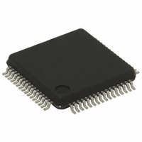
STR752FR2T6 STMicroelectronics, STR752FR2T6 Datasheet - Page 39

STR752FR2T6
Manufacturer Part Number
STR752FR2T6
Description
MCU 32BIT 256KB FLASH 64-LQFP
Manufacturer
STMicroelectronics
Series
STR7r
Datasheet
1.STR750FV0T6.pdf
(84 pages)
Specifications of STR752FR2T6
Core Processor
ARM7
Core Size
32-Bit
Speed
60MHz
Connectivity
CAN, I²C, SPI, SSI, SSP, UART/USART
Peripherals
DMA, PWM, WDT
Number Of I /o
38
Program Memory Size
256KB (256K x 8)
Program Memory Type
FLASH
Ram Size
16K x 8
Voltage - Supply (vcc/vdd)
3 V ~ 5.5 V
Data Converters
A/D 11x10b
Oscillator Type
Internal
Operating Temperature
-40°C ~ 85°C
Package / Case
64-LQFP
Processor Series
STR752x
Core
ARM7TDMI
Data Bus Width
32 bit
Data Ram Size
16 KB
Interface Type
CAN, I2C, SPI, SSI, SSP, USB
Maximum Clock Frequency
60 MHz
Number Of Programmable I/os
38
Number Of Timers
6
Maximum Operating Temperature
+ 85 C
Mounting Style
SMD/SMT
3rd Party Development Tools
EWARM, EWARM-BL, KSDK-STR750-PLUS, MCBSTR750, MCBSTR750U, MCBSTR750UME, MDK-ARM, RL-ARM, ULINK2
Development Tools By Supplier
STR750-MCKIT, STR750-SK/HIT, STR750-SK/IAR, STR750-SK/KEIL, STR750-SK/RAIS, STR750-EVAL, STX-PRO/RAIS, STX-RLINK, STR79-RVDK/CPP, STR79-RVDK, STR79-RVDK/UPG
Minimum Operating Temperature
- 40 C
On-chip Adc
10 bit, 11 Channel
For Use With
MCBSTR750UME - BOARD EVAL MCBSTR750 + ULINK-MEMCBSTR750U - BOARD EVAL MCBSTR750 + ULINK2497-5754 - KIT STARTER IAR STR750497-5753 - KIT STARTER KEIL FOR STR7/STR9497-5752 - KIT STARTER IAR FOR STR7/STR9497-5748 - BOARD EVALUATION FOR STR750XF497-5046 - KIT TOOL FOR ST7/UPSD/STR7 MCU
Lead Free Status / RoHS Status
Lead free / RoHS Compliant
Eeprom Size
-
Lead Free Status / Rohs Status
Details
Other names
497-5653
Available stocks
Company
Part Number
Manufacturer
Quantity
Price
Company:
Part Number:
STR752FR2T6
Manufacturer:
STM
Quantity:
6 600
Company:
Part Number:
STR752FR2T6
Manufacturer:
STMicroelectronics
Quantity:
10 000
STR750Fxx STR751Fxx STR752Fxx STR755Fxx
Typical power consumption
The following measurement conditions apply to
In RUN mode:
●
●
●
●
In WFI Mode:
●
In SLOW mode:
●
In SLOW-WFI mode:
●
In STOP mode:
●
In STANDBY mode:
●
●
Program is executed from Flash (except if especially mentioned). The program consists
of an infinite loop. When f
A standard 4 MHz crystal source is used.
In all cases the PLL is used to multiply the frequency.
All measurements are done in the single supply scheme with internal regulators used
(see
In WFI Mode the measurement conditions are similar to RUN mode (OSC4M and PLL
enabled). In addition, the Flash can be disabled depending on burst mode activation:
–
–
The same program as in RUN mode is executed from Flash. The CPU is clocked by the
FREEOSC, OSC4M, LPOSC or OSC32K. Only EXTIT peripheral is enabled in the
MRCC_PCLKEN register.
In SLOW-WFI, the measurement conditions are similar to SLOW mode (CPU clocked
by a low frequency clock). In addition, the LP_PARAM14 bit is set (FLASH is OFF). The
WFI routine itself is executed from SRAM (it is not allowed to execute a WFI from the
internal FLASH)
Several measurements are given: in the single supply scheme with internal regulators
used (see
Three measurements are given:
–
–
–
STANDBY mode is only supported in the single supply scheme (see
For AHB frequencies greater than 32 MHz, burst mode is activated and the Flash
is kept enabled by setting the WFI_FLASH_EN bit (this bit cannot be reset when
burst mode is activated).
For AHB frequencies less than or equal to 32 MHz, burst mode is deactivated,
WFI_FLASH_EN is reset and the LP_PARAM14 bit is set (Flash is disabled in WFI
mode).
The RTC is disabled, only the consumption of the LPVREG and RSM remain
(almost no leakage currents)
The RTC is running, clocked by a standard 32.768 kHz crystal.
The RTC is running, clocked by the internal Low Power RC oscillator (LPOSC)
Figure
Figure
12)
12): and in the dual supply scheme (see
HCLK
> 32 MHz, burst mode is activated.
Table
15,
Table 16
Figure
and
Electrical parameters
13).
Table
Figure
17.
12)
39/84


