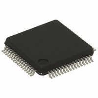
STR752FR2T6 STMicroelectronics, STR752FR2T6 Datasheet - Page 73

STR752FR2T6
Manufacturer Part Number
STR752FR2T6
Description
MCU 32BIT 256KB FLASH 64-LQFP
Manufacturer
STMicroelectronics
Series
STR7r
Datasheet
1.STR750FV0T6.pdf
(84 pages)
Specifications of STR752FR2T6
Core Processor
ARM7
Core Size
32-Bit
Speed
60MHz
Connectivity
CAN, I²C, SPI, SSI, SSP, UART/USART
Peripherals
DMA, PWM, WDT
Number Of I /o
38
Program Memory Size
256KB (256K x 8)
Program Memory Type
FLASH
Ram Size
16K x 8
Voltage - Supply (vcc/vdd)
3 V ~ 5.5 V
Data Converters
A/D 11x10b
Oscillator Type
Internal
Operating Temperature
-40°C ~ 85°C
Package / Case
64-LQFP
Processor Series
STR752x
Core
ARM7TDMI
Data Bus Width
32 bit
Data Ram Size
16 KB
Interface Type
CAN, I2C, SPI, SSI, SSP, USB
Maximum Clock Frequency
60 MHz
Number Of Programmable I/os
38
Number Of Timers
6
Maximum Operating Temperature
+ 85 C
Mounting Style
SMD/SMT
3rd Party Development Tools
EWARM, EWARM-BL, KSDK-STR750-PLUS, MCBSTR750, MCBSTR750U, MCBSTR750UME, MDK-ARM, RL-ARM, ULINK2
Development Tools By Supplier
STR750-MCKIT, STR750-SK/HIT, STR750-SK/IAR, STR750-SK/KEIL, STR750-SK/RAIS, STR750-EVAL, STX-PRO/RAIS, STX-RLINK, STR79-RVDK/CPP, STR79-RVDK, STR79-RVDK/UPG
Minimum Operating Temperature
- 40 C
On-chip Adc
10 bit, 11 Channel
For Use With
MCBSTR750UME - BOARD EVAL MCBSTR750 + ULINK-MEMCBSTR750U - BOARD EVAL MCBSTR750 + ULINK2497-5754 - KIT STARTER IAR STR750497-5753 - KIT STARTER KEIL FOR STR7/STR9497-5752 - KIT STARTER IAR FOR STR7/STR9497-5748 - BOARD EVALUATION FOR STR750XF497-5046 - KIT TOOL FOR ST7/UPSD/STR7 MCU
Lead Free Status / RoHS Status
Lead free / RoHS Compliant
Eeprom Size
-
Lead Free Status / Rohs Status
Details
Other names
497-5653
Available stocks
Company
Part Number
Manufacturer
Quantity
Price
Company:
Part Number:
STR752FR2T6
Manufacturer:
STM
Quantity:
6 600
Company:
Part Number:
STR752FR2T6
Manufacturer:
STMicroelectronics
Quantity:
10 000
STR750Fxx STR751Fxx STR752Fxx STR755Fxx
ADC accuracy vs. negative injection current
Injecting negative current on specific pins listed in
input pin being converted) should be avoided as this significantly reduces the accuracy of
the conversion being performed. It is recommended to add a Schottky diode (pin to ground)
to pins which may potentially inject negative current.
Table 46.
Figure 42. Typical application with ADC
Analog power supply and reference pins
The V
Separation of the digital and analog power pins allow board designers to improve A/D
performance. Conversion accuracy can be impacted by voltage drops and noise in the event
of heavily loaded or badly decoupled power supply lines (see
guidelines on page
a
AIN1/P0.03
AIN2/P0.12
AIN3/P0.17
AIN4/P0.19
AIN5/P0.22
AIN6/P0.23
AIN7/P0.27
AIN8/P0.29
AIN9/P1.04
AIN10/P1.06
AIN11/P1.08
AIN12/P1.11
AIN13/P1.12
AIN14/P1.13
AIN15/P1.14
Analog input
DDA_ADC
V
AIN
List of adjacent pins
and V
R
AIN
74).
SSA_ADC
None
None
P0.11
P0.18 and P0.16
P0.24
None
P2.04
P1.11 and P0.26
P0.30 and P0.28
None
P1.05
P1.04 and P1.13
P2.17 and P0.27
None
P1.14 and P1.01
None
C
AIN
AINx
pins are the analog power supply of the A/D converter cell.
V
DD
V
0.6V
V
0.6V
Related adjacent pins
T
T
Table 46
2kΩ(max)
I
±1μA
L
(generally adjacent to the analog
: General PCB design
10-Bit A/D
Conversion
Electrical parameters
STR75XX
C
3.2pF
ADC
73/84


