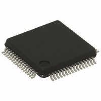
STR752FR2T6 STMicroelectronics, STR752FR2T6 Datasheet - Page 70

STR752FR2T6
Manufacturer Part Number
STR752FR2T6
Description
MCU 32BIT 256KB FLASH 64-LQFP
Manufacturer
STMicroelectronics
Series
STR7r
Datasheet
1.STR750FV0T6.pdf
(84 pages)
Specifications of STR752FR2T6
Core Processor
ARM7
Core Size
32-Bit
Speed
60MHz
Connectivity
CAN, I²C, SPI, SSI, SSP, UART/USART
Peripherals
DMA, PWM, WDT
Number Of I /o
38
Program Memory Size
256KB (256K x 8)
Program Memory Type
FLASH
Ram Size
16K x 8
Voltage - Supply (vcc/vdd)
3 V ~ 5.5 V
Data Converters
A/D 11x10b
Oscillator Type
Internal
Operating Temperature
-40°C ~ 85°C
Package / Case
64-LQFP
Processor Series
STR752x
Core
ARM7TDMI
Data Bus Width
32 bit
Data Ram Size
16 KB
Interface Type
CAN, I2C, SPI, SSI, SSP, USB
Maximum Clock Frequency
60 MHz
Number Of Programmable I/os
38
Number Of Timers
6
Maximum Operating Temperature
+ 85 C
Mounting Style
SMD/SMT
3rd Party Development Tools
EWARM, EWARM-BL, KSDK-STR750-PLUS, MCBSTR750, MCBSTR750U, MCBSTR750UME, MDK-ARM, RL-ARM, ULINK2
Development Tools By Supplier
STR750-MCKIT, STR750-SK/HIT, STR750-SK/IAR, STR750-SK/KEIL, STR750-SK/RAIS, STR750-EVAL, STX-PRO/RAIS, STX-RLINK, STR79-RVDK/CPP, STR79-RVDK, STR79-RVDK/UPG
Minimum Operating Temperature
- 40 C
On-chip Adc
10 bit, 11 Channel
For Use With
MCBSTR750UME - BOARD EVAL MCBSTR750 + ULINK-MEMCBSTR750U - BOARD EVAL MCBSTR750 + ULINK2497-5754 - KIT STARTER IAR STR750497-5753 - KIT STARTER KEIL FOR STR7/STR9497-5752 - KIT STARTER IAR FOR STR7/STR9497-5748 - BOARD EVALUATION FOR STR750XF497-5046 - KIT TOOL FOR ST7/UPSD/STR7 MCU
Lead Free Status / RoHS Status
Lead free / RoHS Compliant
Eeprom Size
-
Lead Free Status / Rohs Status
Details
Other names
497-5653
Available stocks
Company
Part Number
Manufacturer
Quantity
Price
Company:
Part Number:
STR752FR2T6
Manufacturer:
STM
Quantity:
6 600
Company:
Part Number:
STR752FR2T6
Manufacturer:
STMicroelectronics
Quantity:
10 000
Electrical parameters
6.3.11
70/84
USB characteristics
The USB interface is USB-IF certified (Full Speed).
Table 42.
Table 43.
1. All the voltages are measured from the local ground potential.
2. It is important to be aware that the DP/DM pins are not 5 V tolerant. As a consequence, in case of a a
3. R
Figure 41. USB: data signal rise and fall time
Table 44.
Symbol
Symbol
shortcut with Vbus (typ: 5.0V), the protection diodes of the DP/DM pins will be direct biased . This will not
damage the device if not more than 50 mA is sunk for longer than 24 hours but the reliability may be
affected.
V
V
V
V
V
t
Symbol
L
STARTUP
t
CM
OH
t
SE
OL
DI
r
f
is the load connected on the USB drivers
V
V
SS
Data Lines
Differential
CRS
USB startup time
USB characteristics
USB: Full speed electrical characteristics
Differential Input Sensitivity
Differential Common Mode
Static Output Level High
Static Output Level Low
Single Ended Receiver
USB transceiver startup time
Parameter
Threshold
Rise time
Parameter
Fall Time
Range
t
f
Parameter
USB DC Electrical Characteristics
Crossover
(1)
1)
points
Driver characteristics:
Output Levels
Input Levels
STR750Fxx STR751Fxx STR752Fxx STR755Fxx
t
r
R
R
L
Includes V
L
of 1.5 k
Conditions
of 15 k
C
C
Conditions
L
L
I(DP, DM)
=50 pF
=50 pF
Conditions
Ω
Ω
DI
to 3.6V
to V
range
SS
(3)
(3)
Min
4
4
Min.
0.2
0.8
1.3
2.8
(1)(2)
Max
1
Max
20
20
Max.
2.5
2.0
0.3
3.6
(1)(2)
Unit
Unit
µs
ns
ns
Unit
V
V


