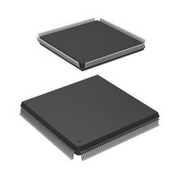
HD6417727F160V Renesas Electronics America, HD6417727F160V Datasheet - Page 280

HD6417727F160V
Manufacturer Part Number
HD6417727F160V
Description
MPU 3V 16K PB-FREE 240-QFP
Manufacturer
Renesas Electronics America
Series
SuperH® SH7700r
Datasheet
1.HD6417727BP100CV.pdf
(1098 pages)
Specifications of HD6417727F160V
Core Processor
SH-3 DSP
Core Size
32-Bit
Speed
160MHz
Connectivity
FIFO, SCI, SIO, SmartCard, USB
Peripherals
DMA, LCD, POR, WDT
Number Of I /o
104
Program Memory Type
ROMless
Ram Size
32K x 8
Voltage - Supply (vcc/vdd)
1.7 V ~ 2.05 V
Data Converters
A/D 6x10b; D/A 2x8b
Oscillator Type
Internal
Operating Temperature
-20°C ~ 75°C
Package / Case
240-QFP
Lead Free Status / RoHS Status
Lead free / RoHS Compliant
Eeprom Size
-
Program Memory Size
-
Available stocks
Company
Part Number
Manufacturer
Quantity
Price
Company:
Part Number:
HD6417727F160V
Manufacturer:
HITACHI
Quantity:
9
Company:
Part Number:
HD6417727F160V
Manufacturer:
Renesas Electronics America
Quantity:
10 000
Part Number:
HD6417727F160V
Manufacturer:
RENESAS/瑞萨
Quantity:
20 000
- Current page: 280 of 1098
- Download datasheet (7Mb)
Section 8 User Break Controller
8.3
8.3.1
The flow from setting of break conditions to user break exception processing is described below:
1. The break addresses and the corresponding ASIDs are loaded in the break address registers
2. When the break conditions are satisfied, the UBC sends a user break request to the interrupt
3. The appropriate condition match flags (SCMFCA, SCMFDA, SCMFCB, and SCMFDB) can
4. There is a chance that the data access break and its following instruction fetch break occur
8.3.2
1. When CPU/instruction fetch/read/word or longword is set in the break bus cycle registers
2. An instruction set for a break before execution breaks when it is confirmed that the instruction
Rev.6.00 Mar. 27, 2009 Page 222 of 1036
REJ09B0254-0600
(BARA and BARB) and break ASID registers (BASRA and BASRB in CCN). The masked
addresses are set in the break address mask registers (BAMRA and BAMRB). The break data
is set in the break data register (BDRB). The masked data is set in the break data mask register
(BDMRB). The breaking bus conditions are set in the break bus cycle registers (BBRA and
BBRB). Three groups of the BBRA and BBRB (CPU cycle/DMAC cycle select, instruction
fetch/data access select, and read/write select) are each set. No user break will be generated if
even one of these groups is set with 00. The respective conditions are set in the bits of the
BRCR.
controller. The break type will be sent to CPU indicating the instruction fetch, pre/post
instruction break, data access break, or on-chip I/O access/LDTLB break. When conditions
match up, the CPU condition match flags (SCMFCA and SCMFCB) and DMAC condition
match flags (SCMFDA and SCMFDB) for the respective channels are set.
be used to check if the set conditions match or not. The matching of the conditions sets flags,
but they are not reset. 0 must first be written to them before they can be used again.
around the same time, there will be only one break request to the CPU, but these two break
channel match flags could both be set.
(BBRA/BBRB), the break condition becomes the CPU instruction fetch cycle. Whether it then
breaks before or after the execution of the instruction can then be selected with the
PCBA/PCBB bits of the break control register (BRCR) for the appropriate channel.
has been fetched and will be executed. This means this feature cannot be used on instructions
fetched by overrun (instructions fetched at a branch or during an interrupt transition, but not to
be executed). When this kind of break is set for the delay slot of a delay branch instruction, the
break is generated prior to execution of the instruction that then first accepts the break.
Meanwhile, the break set for pre-instruction-break on delay slot instruction and post-
instruction-break on SLEEP instruction are also prohibited.
Operation Description
Break on Instruction Fetch Cycle
Flow of the User Break Operation
Related parts for HD6417727F160V
Image
Part Number
Description
Manufacturer
Datasheet
Request
R

Part Number:
Description:
KIT STARTER FOR M16C/29
Manufacturer:
Renesas Electronics America
Datasheet:

Part Number:
Description:
KIT STARTER FOR R8C/2D
Manufacturer:
Renesas Electronics America
Datasheet:

Part Number:
Description:
R0K33062P STARTER KIT
Manufacturer:
Renesas Electronics America
Datasheet:

Part Number:
Description:
KIT STARTER FOR R8C/23 E8A
Manufacturer:
Renesas Electronics America
Datasheet:

Part Number:
Description:
KIT STARTER FOR R8C/25
Manufacturer:
Renesas Electronics America
Datasheet:

Part Number:
Description:
KIT STARTER H8S2456 SHARPE DSPLY
Manufacturer:
Renesas Electronics America
Datasheet:

Part Number:
Description:
KIT STARTER FOR R8C38C
Manufacturer:
Renesas Electronics America
Datasheet:

Part Number:
Description:
KIT STARTER FOR R8C35C
Manufacturer:
Renesas Electronics America
Datasheet:

Part Number:
Description:
KIT STARTER FOR R8CL3AC+LCD APPS
Manufacturer:
Renesas Electronics America
Datasheet:

Part Number:
Description:
KIT STARTER FOR RX610
Manufacturer:
Renesas Electronics America
Datasheet:

Part Number:
Description:
KIT STARTER FOR R32C/118
Manufacturer:
Renesas Electronics America
Datasheet:

Part Number:
Description:
KIT DEV RSK-R8C/26-29
Manufacturer:
Renesas Electronics America
Datasheet:

Part Number:
Description:
KIT STARTER FOR SH7124
Manufacturer:
Renesas Electronics America
Datasheet:

Part Number:
Description:
KIT STARTER FOR H8SX/1622
Manufacturer:
Renesas Electronics America
Datasheet:

Part Number:
Description:
KIT DEV FOR SH7203
Manufacturer:
Renesas Electronics America
Datasheet:


