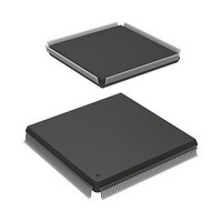
HD6417727F160V Renesas Electronics America, HD6417727F160V Datasheet - Page 970

HD6417727F160V
Manufacturer Part Number
HD6417727F160V
Description
MPU 3V 16K PB-FREE 240-QFP
Manufacturer
Renesas Electronics America
Series
SuperH® SH7700r
Datasheet
1.HD6417727BP100CV.pdf
(1098 pages)
Specifications of HD6417727F160V
Core Processor
SH-3 DSP
Core Size
32-Bit
Speed
160MHz
Connectivity
FIFO, SCI, SIO, SmartCard, USB
Peripherals
DMA, LCD, POR, WDT
Number Of I /o
104
Program Memory Type
ROMless
Ram Size
32K x 8
Voltage - Supply (vcc/vdd)
1.7 V ~ 2.05 V
Data Converters
A/D 6x10b; D/A 2x8b
Oscillator Type
Internal
Operating Temperature
-20°C ~ 75°C
Package / Case
240-QFP
Lead Free Status / RoHS Status
Lead free / RoHS Compliant
Eeprom Size
-
Program Memory Size
-
Available stocks
Company
Part Number
Manufacturer
Quantity
Price
Company:
Part Number:
HD6417727F160V
Manufacturer:
HITACHI
Quantity:
9
Company:
Part Number:
HD6417727F160V
Manufacturer:
Renesas Electronics America
Quantity:
10 000
Part Number:
HD6417727F160V
Manufacturer:
RENESAS/瑞萨
Quantity:
20 000
- Current page: 970 of 1098
- Download datasheet (7Mb)
Section 30 PC Card Controller (PCC)
30.3.3
External Bus Frequency Limit when Using PC Card: According to the PC card standard, the
attribute memory access time is specified as 600 ns (3.3 V)/300 ns (5 V). Therefore, when the
SH7727 accesses attribute memory, the bus cycle must be coordinated with the PC card interface
timing. In the SH7727, the timing can be adjusted by setting the TED and TEH values in the PCR
register, and the number of waits and number of idle states in the WCR1 and WCR2 registers,
allowing a PC card to be used within the above frequency ranges.
The common memory access time and I/O access time (based on the IORD and IOWR signals) are
also similarly specified (see table below), and a PC card must be used within the above ranges in
order to satisfy all these specifications.
PC Card Space
Attribute memory
Common memory
I/O space
(–IORD/–IOWR pulse width)
Pin Function Control and Card Type Switching: When setting pin function controller pin
functions to dedicated PC card use ("other function"), the disabled state should first be set in the
card status change interrupt enable register (PCC0CSCIER). Also, the card status change register
(PCC0CSCR) must be cleared after the setting has been made. However, this restriction does not
apply to the card detection pins (CD1, CD2).
When changing the card type bit (P0PCCT) in the area 6 general control register (PCC0GCR), the
disabled state should first be set in the card status change interrupt enable register
(PCC0CSCIER). Also, the card status change register (PCC0CSCR) must be cleared after the
setting has been made.
Reason: When PC card controller settings are modified, the functions of PC card pins that
Rev.6.00 Mar. 27, 2009 Page 912 of 1036
REJ09B0254-0600
Usage Notes
generate various interrupts change, with the result that unnecessary interrupts may be
generated.
Access Time (5 V Operation)
300 ns
250 ns
165 ns
Access Time (3.3 V Operation)
600 ns
600 ns
165 ns
Related parts for HD6417727F160V
Image
Part Number
Description
Manufacturer
Datasheet
Request
R

Part Number:
Description:
KIT STARTER FOR M16C/29
Manufacturer:
Renesas Electronics America
Datasheet:

Part Number:
Description:
KIT STARTER FOR R8C/2D
Manufacturer:
Renesas Electronics America
Datasheet:

Part Number:
Description:
R0K33062P STARTER KIT
Manufacturer:
Renesas Electronics America
Datasheet:

Part Number:
Description:
KIT STARTER FOR R8C/23 E8A
Manufacturer:
Renesas Electronics America
Datasheet:

Part Number:
Description:
KIT STARTER FOR R8C/25
Manufacturer:
Renesas Electronics America
Datasheet:

Part Number:
Description:
KIT STARTER H8S2456 SHARPE DSPLY
Manufacturer:
Renesas Electronics America
Datasheet:

Part Number:
Description:
KIT STARTER FOR R8C38C
Manufacturer:
Renesas Electronics America
Datasheet:

Part Number:
Description:
KIT STARTER FOR R8C35C
Manufacturer:
Renesas Electronics America
Datasheet:

Part Number:
Description:
KIT STARTER FOR R8CL3AC+LCD APPS
Manufacturer:
Renesas Electronics America
Datasheet:

Part Number:
Description:
KIT STARTER FOR RX610
Manufacturer:
Renesas Electronics America
Datasheet:

Part Number:
Description:
KIT STARTER FOR R32C/118
Manufacturer:
Renesas Electronics America
Datasheet:

Part Number:
Description:
KIT DEV RSK-R8C/26-29
Manufacturer:
Renesas Electronics America
Datasheet:

Part Number:
Description:
KIT STARTER FOR SH7124
Manufacturer:
Renesas Electronics America
Datasheet:

Part Number:
Description:
KIT STARTER FOR H8SX/1622
Manufacturer:
Renesas Electronics America
Datasheet:

Part Number:
Description:
KIT DEV FOR SH7203
Manufacturer:
Renesas Electronics America
Datasheet:


