HD6417032F20 Renesas Electronics America, HD6417032F20 Datasheet - Page 416
HD6417032F20
Manufacturer Part Number
HD6417032F20
Description
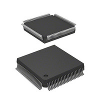
IC SUPERH MPU ROMLESS 112QFP
Manufacturer
Renesas Electronics America
Series
SuperH® SH7030r
Datasheet
1.HD6417034AFI20.pdf
(689 pages)
Specifications of HD6417032F20
Core Processor
SH-1
Core Size
32-Bit
Speed
20MHz
Connectivity
EBI/EMI, SCI
Peripherals
DMA, POR, PWM, WDT
Number Of I /o
32
Program Memory Type
ROMless
Ram Size
4K x 8
Voltage - Supply (vcc/vdd)
4.5 V ~ 5.5 V
Data Converters
A/D 8x10b
Oscillator Type
Internal
Operating Temperature
-20°C ~ 75°C
Package / Case
112-QFP
Lead Free Status / RoHS Status
Contains lead / RoHS non-compliant
Eeprom Size
-
Program Memory Size
-
Available stocks
Company
Part Number
Manufacturer
Quantity
Price
Company:

Part Number:
HD6417032F20
Manufacturer:
HIT
Quantity:
5 510
Company:
Part Number:
HD6417032F20
Manufacturer:
AMCC
Quantity:
5 510
Company:
Part Number:
HD6417032F20
Manufacturer:
Renesas Electronics America
Quantity:
10 000
Part Number:
HD6417032F20
Manufacturer:
HITACHI/日立
Quantity:
20 000
Company:
Part Number:
HD6417032F20V
Manufacturer:
TI
Quantity:
201


Section 13 Serial Communication Interface (SCI)
In receiving, the SCI operates as follows:
1. The SCI monitors the receive data line. When it detects a start bit (0), the SCI synchronizes
2. Receive data is shifted into RSR in order from the LSB to the MSB.
3. The parity bit and stop bit are received. After receiving these bits, the SCI makes the following
2.
Figure 13.8 shows an example of SCI receive operation in asynchronous mode.
Table 13.11 Receive Error Conditions and SCI Operation
Receive Error
Overrun error
Framing error
Parity error
Rev. 7.00 Jan 31, 2006 page 388 of 658
REJ09B0272-0700
internally and starts receiving.
checks:
a. Parity check: The number of 1s in the receive data must match the even or odd parity
b. Stop bit check: The stop bit value must be 1. If there are two stop bits, only the first stop bit
c. Status check: RDRF must be 0 so that receive data can be loaded from RSR into RDR.
Note:
After setting RDRF to 1, if the receive-data-full interrupt enable bit (RIE) is set to 1 in SCR,
the SCI requests a receive-data-full interrupt (RXI). If one of the error flags (ORER, PER, or
FER) is set to 1 and the receive-data-full interrupt enable bit (RIE) in SCR is also set to 1, the
SCI requests a receive-error interrupt (ERI).
setting of the O/E bit in SMR.
is checked.
If these checks all pass, the SCI sets RDRF to 1 and stores the received data in RDR. If one
of the checks fails (receive error), the SCI operates as indicated in table 13.11.
When a receive error flag is set, further receiving is disabled. The RDRF bit is not
set to 1. Be sure to clear the error flags.
Abbreviation
ORER
FER
PER
Condition
RDRF is still set to 1 in SSR
Stop bit is 0
even/odd parity setting in SMR
Receiving of next data ends while
Parity of receive data differs from
Data Transfer
Receive data not loaded
from RSR into RDR
Receive data loaded from
RSR into RDR
Receive data loaded from
RSR into RDR
Related parts for HD6417032F20
Image
Part Number
Description
Manufacturer
Datasheet
Request
R

Part Number:
Description:
KIT STARTER FOR M16C/29
Manufacturer:
Renesas Electronics America
Datasheet:

Part Number:
Description:
KIT STARTER FOR R8C/2D
Manufacturer:
Renesas Electronics America
Datasheet:

Part Number:
Description:
R0K33062P STARTER KIT
Manufacturer:
Renesas Electronics America
Datasheet:

Part Number:
Description:
KIT STARTER FOR R8C/23 E8A
Manufacturer:
Renesas Electronics America
Datasheet:

Part Number:
Description:
KIT STARTER FOR R8C/25
Manufacturer:
Renesas Electronics America
Datasheet:

Part Number:
Description:
KIT STARTER H8S2456 SHARPE DSPLY
Manufacturer:
Renesas Electronics America
Datasheet:

Part Number:
Description:
KIT STARTER FOR R8C38C
Manufacturer:
Renesas Electronics America
Datasheet:

Part Number:
Description:
KIT STARTER FOR R8C35C
Manufacturer:
Renesas Electronics America
Datasheet:

Part Number:
Description:
KIT STARTER FOR R8CL3AC+LCD APPS
Manufacturer:
Renesas Electronics America
Datasheet:
Part Number:
Description:
KIT STARTER FOR RX610
Manufacturer:
Renesas Electronics America
Datasheet:

Part Number:
Description:
KIT STARTER FOR R32C/118
Manufacturer:
Renesas Electronics America
Datasheet:

Part Number:
Description:
KIT DEV RSK-R8C/26-29
Manufacturer:
Renesas Electronics America
Datasheet:

Part Number:
Description:
KIT STARTER FOR SH7124
Manufacturer:
Renesas Electronics America
Datasheet:

Part Number:
Description:
KIT STARTER FOR H8SX/1622
Manufacturer:
Renesas Electronics America
Datasheet:

Part Number:
Description:
KIT DEV FOR SH7203
Manufacturer:
Renesas Electronics America
Datasheet: