M37542F8FP Renesas Electronics America, M37542F8FP Datasheet - Page 116
M37542F8FP
Manufacturer Part Number
M37542F8FP
Description
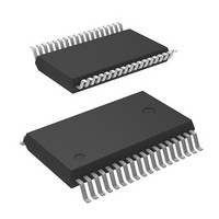
IC 740 MCU FLASH 32K 36SSOP
Manufacturer
Renesas Electronics America
Series
740/38000r
Datasheet
1.M37542F8FPU0.pdf
(124 pages)
Specifications of M37542F8FP
Core Processor
740
Core Size
8-Bit
Speed
8MHz
Connectivity
SIO, UART/USART
Peripherals
POR, WDT
Number Of I /o
29
Program Memory Size
32KB (32K x 8)
Program Memory Type
FLASH
Ram Size
1K x 8
Voltage - Supply (vcc/vdd)
2.2 V ~ 5.5 V
Data Converters
A/D 8x10b
Oscillator Type
Internal
Operating Temperature
-20°C ~ 85°C
Package / Case
36-SSOP
Lead Free Status / RoHS Status
Contains lead / RoHS non-compliant
Eeprom Size
-
Available stocks
Company
Part Number
Manufacturer
Quantity
Price

Part Number:
M37542F8FP
Manufacturer:
MIT
Quantity:
20 000
Company:
Part Number:
M37542F8FP#U0
Manufacturer:
TI
Quantity:
109


7542 Group
Notes on Serial I/O1
1. I/O pin function when serial I/O1 is enabled.
The pin functions of P1
follows according to the setting values of a serial I/O1 mode selec-
tion bit (bit 6 of serial I/O1 control register (address 1A
serial I/O1 synchronous clock selection bit (bit 1 of serial I/O1 con-
trol register).
(1) Serial I/O1 mode selection bit → “1” :
Clock synchronous type serial I/O is selected.
• Setup of a serial I/O1 synchronous clock selection bit
“0” : P1
“1” : P1
• Setup of a S
“0” : P1
“1” : P1
(2) Serial I/O1 mode selection bit → “0” :
Clock asynchronous (UART) type serial I/O is selected.
• Setup of a serial I/O1 synchronous clock selection bit
“0”: P1
“1”: P1
• When clock asynchronous (UART) type serial I/O is selected, it
Note on Bus Collision Detection
When serial I/O1 is operating at half-duplex communication, set
bus collision detection interrupt to be disabled.
Rev.3.03
REJ03B0006-0303
functions P1
2
2
2
2
3
3
pin can be used as a normal I/O pin.
pin turns into an input pin of an external clock.
pin turns into an output pin of a synchronous clock.
pin turns into an input pin of a synchronous clock.
pin can be used as a normal I/O pin.
pin turns into a S
RDY1
3
Jul 11, 2008
pin. It can be used as a normal I/O pin.
output enable bit (SRDY)
2
/S
RDY1
CLK1
output pin.
and P1
Page 114 of 117
3
/S
RDY1
are switched to as
16
)) and a
Notes on Serial I/O2
1. I/O pin function when serial I/O2 is enabled
The pin functions of P0
follows according to the setting values of a serial I/O2 mode selec-
tion bit (bit 6 of serial I/O2 control register (address 30
serial I/O2 synchronous clock selection bit (bit 2 of serial I/O2 con-
trol register).
(1) Serial I/O2 mode selection bit → “1” :
Clock synchronous type serial I/O is selected.
• Setup of a serial I/O2 synchronous clock selection bit
“0” : P0
“1” : P0
• Setup of a S
“0” : P0
“1” : P0
(2) Serial I/O2 mode selection bit → “0” :
Clock asynchronous (UART) type serial I/O is selected.
• Setup of a serial I/O2 synchronous clock selection bit
“0”: P0
“1”: P0
• When clock asynchronous (UART) type serial I/O is selected, it
functions P0
6
6
6
6
7
7
pin can be used as a normal I/O pin.
pin turns into an input pin of an external clock.
pin turns into an output pin of a synchronous clock.
pin turns into an input pin of a synchronous clock.
pin can be used as a normal I/O pin.
pin turns into a S
RDY2
7
pin. It can be used as a normal I/O pin.
output enable bit (SRDY)
6
/S
RDY2
CLK2
output pin.
and P0
7
/S
RDY2
are switched to as
16
)) and a
Related parts for M37542F8FP
Image
Part Number
Description
Manufacturer
Datasheet
Request
R

Part Number:
Description:
M37542 EMULATOR KIT (EK) FOR PC4
Manufacturer:
Renesas Electronics America

Part Number:
Description:
KIT STARTER FOR M16C/29
Manufacturer:
Renesas Electronics America
Datasheet:

Part Number:
Description:
KIT STARTER FOR R8C/2D
Manufacturer:
Renesas Electronics America
Datasheet:

Part Number:
Description:
R0K33062P STARTER KIT
Manufacturer:
Renesas Electronics America
Datasheet:

Part Number:
Description:
KIT STARTER FOR R8C/23 E8A
Manufacturer:
Renesas Electronics America
Datasheet:

Part Number:
Description:
KIT STARTER FOR R8C/25
Manufacturer:
Renesas Electronics America
Datasheet:
Part Number:
Description:
KIT STARTER H8S2456 SHARPE DSPLY
Manufacturer:
Renesas Electronics America
Datasheet:

Part Number:
Description:
KIT STARTER FOR R8C38C
Manufacturer:
Renesas Electronics America
Datasheet:

Part Number:
Description:
KIT STARTER FOR R8C35C
Manufacturer:
Renesas Electronics America
Datasheet:

Part Number:
Description:
KIT STARTER FOR R8CL3AC+LCD APPS
Manufacturer:
Renesas Electronics America
Datasheet:
Part Number:
Description:
KIT STARTER FOR RX610
Manufacturer:
Renesas Electronics America
Datasheet:

Part Number:
Description:
KIT STARTER FOR R32C/118
Manufacturer:
Renesas Electronics America
Datasheet:

Part Number:
Description:
KIT DEV RSK-R8C/26-29
Manufacturer:
Renesas Electronics America
Datasheet:

Part Number:
Description:
KIT STARTER FOR SH7124
Manufacturer:
Renesas Electronics America
Datasheet:

Part Number:
Description:
KIT STARTER FOR H8SX/1622
Manufacturer:
Renesas Electronics America
Datasheet: