M37542F8FP Renesas Electronics America, M37542F8FP Datasheet - Page 51
M37542F8FP
Manufacturer Part Number
M37542F8FP
Description
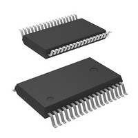
IC 740 MCU FLASH 32K 36SSOP
Manufacturer
Renesas Electronics America
Series
740/38000r
Datasheet
1.M37542F8FPU0.pdf
(124 pages)
Specifications of M37542F8FP
Core Processor
740
Core Size
8-Bit
Speed
8MHz
Connectivity
SIO, UART/USART
Peripherals
POR, WDT
Number Of I /o
29
Program Memory Size
32KB (32K x 8)
Program Memory Type
FLASH
Ram Size
1K x 8
Voltage - Supply (vcc/vdd)
2.2 V ~ 5.5 V
Data Converters
A/D 8x10b
Oscillator Type
Internal
Operating Temperature
-20°C ~ 85°C
Package / Case
36-SSOP
Lead Free Status / RoHS Status
Contains lead / RoHS non-compliant
Eeprom Size
-
Available stocks
Company
Part Number
Manufacturer
Quantity
Price

Part Number:
M37542F8FP
Manufacturer:
MIT
Quantity:
20 000
Company:
Part Number:
M37542F8FP#U0
Manufacturer:
TI
Quantity:
109


7542 Group
[Transmit buffer register 1/receive buffer register 1 (TB1/
RB1)] 0018
The transmit buffer register and the receive buffer register are lo-
cated at the same address. The transmit buffer is write-only and
the receive buffer is read-only. If a character bit length is 7 bits, the
MSB of data stored in the receive buffer is “0”.
[Serial I/O1 status register (SIO1STS)] 0019
The read-only serial I/O1 status register consists of seven flags
(bits 0 to 6) which indicate the operating status of the serial I/O1
function and various errors.
Three of the flags (bits 4 to 6) are valid only in UART mode.
The receive buffer full flag (bit 1) is cleared to “0” when the receive
buffer register is read.
If there is an error, it is detected at the same time that data is
transferred from the receive shift register to the receive buffer reg-
ister, and the receive buffer full flag is set. A write to the serial I/O1
status register clears all the error flags OE, PE, FE, and SE (bit 3
to bit 6, respectively). Writing “0” to the serial I/O1 enable bit SIOE
(bit 7 of the serial I/O1 control register) also clears all the status
flags, including the error flags.
Bits 0 to 6 of the serial I/O1 status register are initialized to “0” at
reset, but if the transmit enable bit of the serial I/O1 control regis-
ter has been set to “1”, the transmit shift completion flag (bit 2)
and the transmit buffer empty flag (bit 0) become “1”.
[Serial I/O1 control register (SIO1CON)] 001A
The serial I/O1 control register consists of eight control bits for the
serial I/O1 function.
[UART1 control register (UART1CON)] 001B
The UART1 control register consists of four control bits (bits 0 to
3) which are valid when asynchronous serial I/O is selected and
set the data format of an data transfer and one bit (bit 4) which is
always valid and sets the output structure of the P1
[Baud rate generator 1 (BRG1)] 001C
The baud rate generator determines the baud rate for serial transfer.
The baud rate generator divides the frequency of the count source
by 1/(n + 1), where n is the value written to the baud rate generator.
Rev.3.03
REJ03B0006-0303
16
Jul 11, 2008
Page 49 of 117
16
16
16
16
1
/TxD
1
pin.
• Serial I/O interrupt
When setting the transmit enable bit to “1”, the serial I/O transmit
interrupt request bit is automatically set to “1”. When not requiring
the interrupt occurrence synchronized with the transmission en-
abled, take the following sequence.
• I/O pin function when serial I/O1 is enabled.
The functions of P1
of a serial I/O1 mode selection bit and a serial I/O1 synchronous
clock selection bit as follows.
(1) Serial I/O1 mode selection bit → “1” :
Clock synchronous type serial I/O is selected.
Setup of a serial I/O1 synchronous clock selection bit
“0” : P1
“1” : P1
Setup of a S
“0” : P1
“1” : P1
(2) Serial I/O1 mode selection bit → “0” :
Clock asynchronous (UART) type serial I/O is selected.
Setup of a serial I/O1 synchronous clock selection bit
“0”: P1
“1”: P1
When clock asynchronous (UART) type serial I/O is selected, it is
P1
Notes on Serial I/O1
Set the serial I/O transmit interrupt enable bit to “0” (disabled).
Set the transmit enable bit to “1”.
Set the serial I/O transmit interrupt request bit to “0” after 1 or
more instructions have been executed.
Set the serial I/O transmit interrupt enable bit to “1” (enabled).
3
pin. It can be used as a normal I/O pin.
2
2
2
2
3
3
pin can be used as a normal I/O pin.
pin turns into an input pin of an external clock.
pin turns into an output pin of a synchronous clock.
pin turns into an input pin of a synchronous clock.
pin can be used as a normal I/O pin.
pin turns into a S
RDY1
output enable bit (SRDY)
2
and P1
RDY1
3
are switched with the setting values
output pin.
Related parts for M37542F8FP
Image
Part Number
Description
Manufacturer
Datasheet
Request
R

Part Number:
Description:
M37542 EMULATOR KIT (EK) FOR PC4
Manufacturer:
Renesas Electronics America

Part Number:
Description:
KIT STARTER FOR M16C/29
Manufacturer:
Renesas Electronics America
Datasheet:

Part Number:
Description:
KIT STARTER FOR R8C/2D
Manufacturer:
Renesas Electronics America
Datasheet:

Part Number:
Description:
R0K33062P STARTER KIT
Manufacturer:
Renesas Electronics America
Datasheet:

Part Number:
Description:
KIT STARTER FOR R8C/23 E8A
Manufacturer:
Renesas Electronics America
Datasheet:

Part Number:
Description:
KIT STARTER FOR R8C/25
Manufacturer:
Renesas Electronics America
Datasheet:
Part Number:
Description:
KIT STARTER H8S2456 SHARPE DSPLY
Manufacturer:
Renesas Electronics America
Datasheet:

Part Number:
Description:
KIT STARTER FOR R8C38C
Manufacturer:
Renesas Electronics America
Datasheet:

Part Number:
Description:
KIT STARTER FOR R8C35C
Manufacturer:
Renesas Electronics America
Datasheet:

Part Number:
Description:
KIT STARTER FOR R8CL3AC+LCD APPS
Manufacturer:
Renesas Electronics America
Datasheet:
Part Number:
Description:
KIT STARTER FOR RX610
Manufacturer:
Renesas Electronics America
Datasheet:

Part Number:
Description:
KIT STARTER FOR R32C/118
Manufacturer:
Renesas Electronics America
Datasheet:

Part Number:
Description:
KIT DEV RSK-R8C/26-29
Manufacturer:
Renesas Electronics America
Datasheet:

Part Number:
Description:
KIT STARTER FOR SH7124
Manufacturer:
Renesas Electronics America
Datasheet:

Part Number:
Description:
KIT STARTER FOR H8SX/1622
Manufacturer:
Renesas Electronics America
Datasheet: